54
Installation
Mounting the rope guard
TK Elevator
BA, TW45 | 6231003860 | 03/2023
5. Position the frame in accordance with general arrangement drawing on
the insulation elements.
6. Lift the machine onto the frame with lifting gear.
The traction sheave must rest on the diverter pulley side.
7. Move the machine sideways on the base frame until the required ASL di-
mension (parallel gap between the ropes at the rope departure) is
reached.
8. Bolt the machine onto the frame, whereby the machine housing must not
be tensioned.
Use the supplied shims for compensation.
9. Align the rope grooves of the traction sheave and diverter pulley in paral-
lel.
10. Tighten the bolts with the required torque.
11. Plumb the rope departure on the rope pulley and/or mounting on elevator
car and counterweight.
12. With a horizontal rope departure, the gear housing on the machine base
frame is to be secured against shifting by means of end stops.
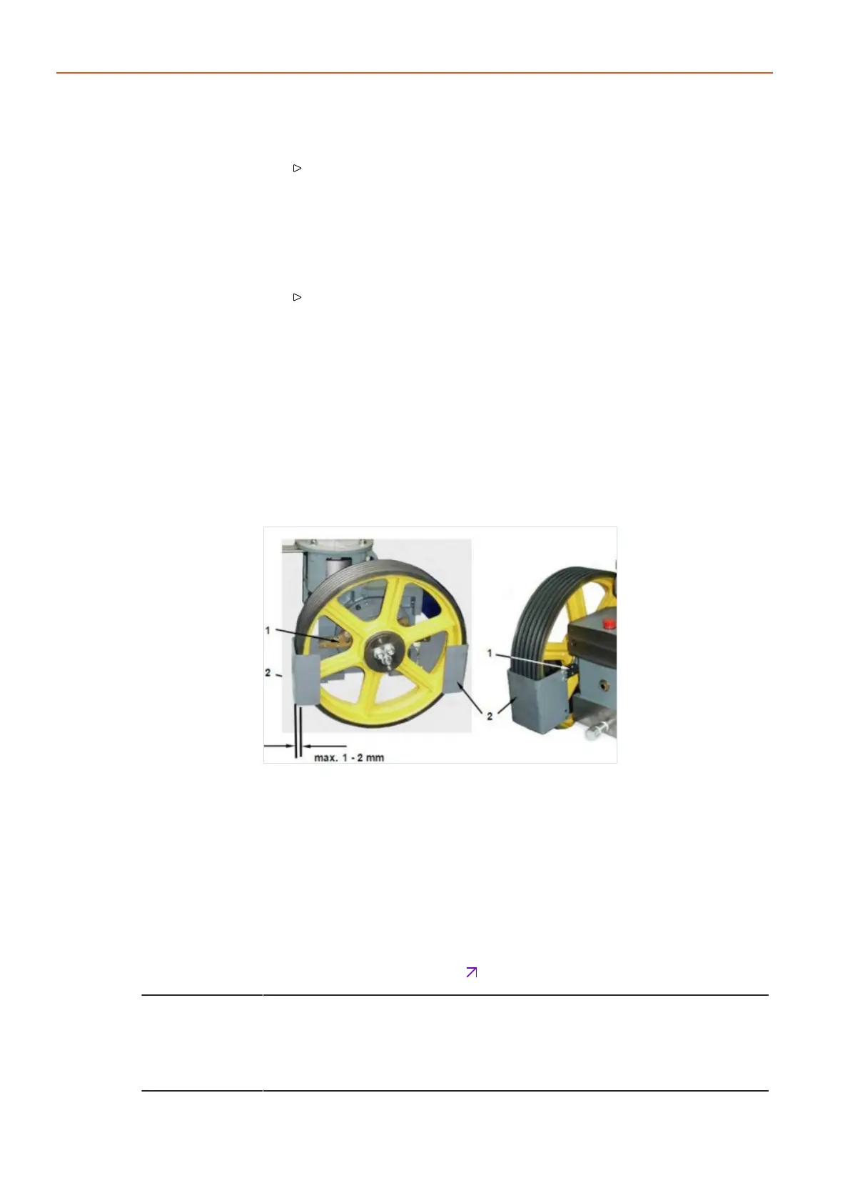
6.4 Mounting the rope guard
Fig.26 ATR_2_21_0051_0
1. Use the enclosed screws to bolt the rope guard onto the rope guard car-
rier.
2. Pivot the rope guard carrier to set the guard in such a way that the gap
between the rope and guard on the rope run-in and run-out side of the
traction sheave is as small as possible (1-2 mm).
3. Adapt the inclined pulling location of the rope guard carrier by remounting
the changed rope pull direction.
4. Align the winch and tighten the securing bolts of the rope guard carrier
with the prescribed torque
Chap.10.1P.75.
For machines with rope run-in direction of 0 - 90° above the horizontal (e.g.:
(machine arrangement up/down beside), an additional rope guard is required to
prevent foreign bodies entering between the rope and groove. If the rope run-in
zone is protected within the machine base frame, the function "protection
against injury" is not required.