Installation
Setting up the machine base frame 51
TK Elevator
BA, TW45 | 6231003860 | 03/2023
6 Installation
6.1 Setting up the machine base frame
To reduce noise and sound transmission, we offer insulation elements that
can be inserted between the frame supports and floor. These differ according
to the type of mounting:
▪ A rubber block 100 x 100 x 50 high without base is used to mount the
drive on the machine room floor without a cement floor or directly sur-
face-mounted on the cement floor.
▪ For installation on cement floor, packing cast into cement floor (thickness
≤ 60 mm). The packing component must be cast in when installing the ce-
ment floor. A rubber block 100 x 100 x 50 with additional packing 140 x
140 x 80 mm is used here.
The number and arrangement of rubber elements is based on the total load
and the distance between the rope lengths (ASL dimension = distance
between rope departures).
When arranging the supports, the overall centre of gravity must lie within the
rubber elements.
The arrangement under the machine base frame should be such that the
stress and/or buffering of the insulation elements (maximum difference 3 - 5
mm) is as even as possible.
6.2 Aligning the machine
The machine is to be set up according to the general arrangement drawing.
The rope departure from the traction sheave is to be aligned plumb to the el-
evator car mounting or the elevator car rope pulley and the counterweight ac-
cording to the drawing. With load applied to the ropes, the machine should be
aligned vertically on its installation surface. Irregularities are to be balanced
out by inserting shims under the floor support.
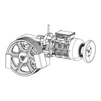
SA9 traction sheave in the shaft, machine with extended traction sheave shaft
and pedestal bearing.
1. Fitting and mounting of the compensation supports.
2. Horizontal alignment of the traction sheave shaft.
3. Align the bearings of the machine and the outside bearing exactly.