Work on the product
Replacing the traction sheave 67
TK Elevator
BA, TW45 | 6231003860 | 03/2023
Installation of the traction sheave
1. Clean the shaft end and traction sheave bore hole (free of oil, grease,
paint)
Do
not
apply grease or oil to the shaft and hub.
2. Place the new traction sheave on the conical shaft end of the motor shaft.
3. Align the locations of the feather key and groove in relation to one an-
other.
4. Push the traction sheave onto the motor shaft.
1. Use the supplied
new
microencapsulated screw and detent edged wash-
ers to attach the tension disc to the motor shaft at the inner circle of
holes.
2. Comply with the prescribed tightening torque of 90 Nm.
3. Comply with the prescribed tightening torque of 160 Nm (with NBS emer-
gency brake system 190 Nm).
4. Comply with the prescribed tightening torque of 250 Nm.
Compare torque with drawing.
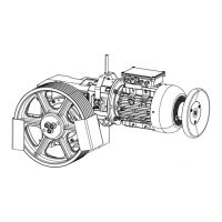
Fig.36 ATR_2_12_0063_0
Item Designation Item Designation
1 Fastening screw 2 Hole for forcing screw
3 Traction sheave 4 Tension disc
5 Rope guard plate 6
1. Release the mounting of the traction sheave from the lifting gear.
2. Hang up the ropes on the traction sheave.
3. Fit the rope guard plates.
4. Align the rope guard plates.
5. Remove the securing devices from the car and counterweight.