Installation and Operational Instructions for
ROBA-stop
®
-Z Type 892.101.0
Size 125 (E073 01 046 000 4 EN)
18/05/2022 TK/HW/SU Chr. Mayr GmbH + Co. KG
Eichenstraße 1, D-87665 Mauerstetten, Germany
Phone: +49 8341 804-0, Fax: +49 8341 804-421
Page 8 of 16 www.mayr.com, E-Mail: public.mayr@mayr.de
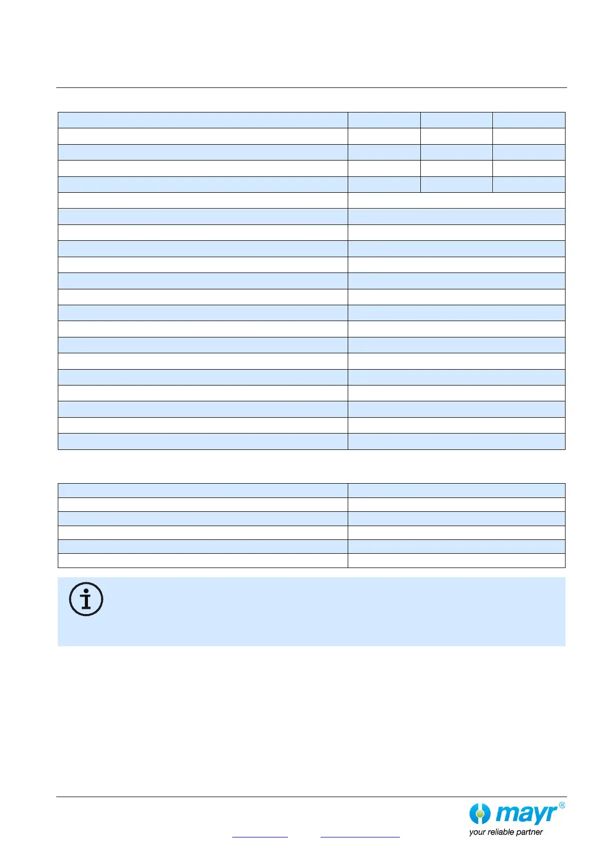
Table 1: Technical Data
Coil power (nominal power at 20°C)
Coil power on overexcitation
Nominal braking torque (+60 %)
Rotor thickness, new condition
Nominal air gap “a” total (braked)
Limit air gap “a” for rotor replacement
Inspection air gap “b” released, per single circuit
Tightening torque Item 1.2
Tightening torque Item 16
Tightening torque Item 18.3
Tightening torque Item 18.6
Tightening torque Item 18.7
Tightening torque Item 18.9
Max. permitted friction work for both rotors at a speed of 1800 rpm
Table 2: Switching Times
5)
Referring to the nominal braking torque
6)
Referring to the effective braking torque
The stated switching times can only be achieved using the respective correct electrical wiring. This also refers to the
protection circuit for brake control and the response delay times of all control components. If the brake is operated using
overexcitation, the respective switch-on and switch-off times for overexcitation must be taken into account.
The use of varistors for spark quenching increases the DC-side switching times.