EasyManua.ls Logo

Toa D-901 - Contact Controls

Toa D-901
94 pages
Print Icon
To Next Page IconTo Next Page
To Previous Page IconTo Previous Page
Loading...
81
[Connections to the output channel VCA terminal]
1 OUT CH 1
RJ45
D-984VC
[OUT CH 1 - 4]
2 OUT CH 2
3 OUT CH 3
4 C (GND)
5 V (+5 V)
6 OUT CH 4
7 V (+5 V)
8 C (GND)
D-901's volume
Minimum level
+5 V
0 V
16.5.3. Contact controls (5) (8)
Preset memory recall function is assigned to the contact input and output pins at the factory. To change this
function assignment to give channel ON/OFF or line input selection, refer to p. 69.
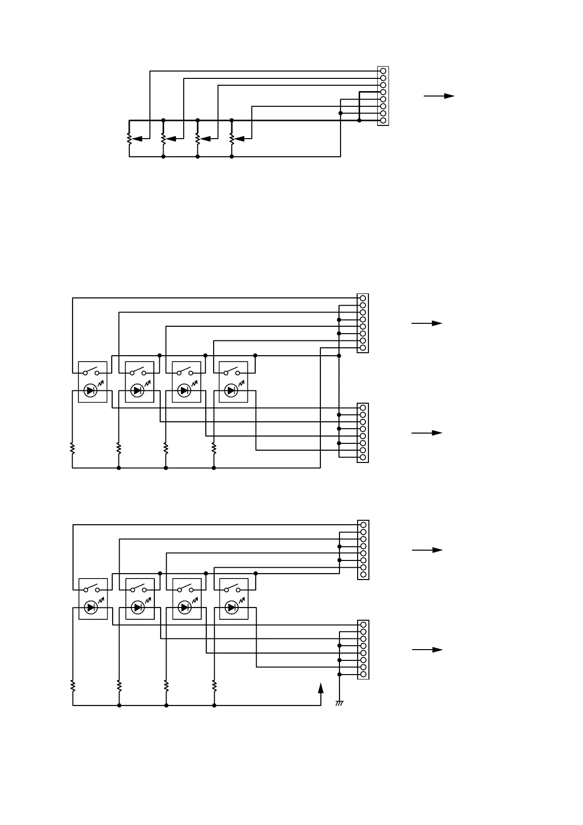
The V pins of the control input terminals can be used for LED connections. To do this, connect the contact
COM pins to use out of the C1 4 pins of the control output (7) or the C5 8 pins of the control output (8) to
the C pins of the control input (5) or (6). (The diagram below is an example where the control output's C1
4 pins are connected to the control input's C pins.)
1 CTRL IN 1
RJ45
D-984VC's control
input terminal (5)
[CTRL IN 1 - 4]
2 C (GND)
3 CTRL IN 2
4 C (GND)
5 CTRL IN 3
6 C (GND)
7 CTRL IN 4
8 V (+5 V)
1 CTRL OUT 1
RJ45
D-984VC's control
output terminal (7)
[CTRL OUT 1 - 4]
2 C1
3 CTRL OUT 2
4 C2
5 CTRL OUT 3
6 C3
7 CTRL OUT 4
8 C4
The current capacity is 40 mA per V pin. When more current is needed, connect a power supply separately
as shown below.
1 CTRL IN 1
RJ45
D-984VC's control
input terminal (5)
[CTRL IN 1 - 4]
2 C (GND)
3 CTRL IN 2
4 C (GND)
5 CTRL IN 3
6 C (GND)
7 CTRL IN 4
8 V (+5 V)
1 CTRL OUT 1
RJ45
D-984VC's control
output terminal (7)
[CTRL OUT 1 - 4]
2 C1
3 CTRL OUT 2
4 C2
5 CTRL OUT 3
6 C3
7 CTRL OUT 4
8 C4
DC
Never connect the V pins of control inputs (5) and (6) to the V pins of VCA pins (1) (4) as the sound
volume may be affected due to voltage drop caused by these connections.

Table of Contents

Other manuals for Toa D-901

Related product manuals