3-80
Chapter 3
INSTALLATION AND SETTING PROCEDURES (HARDWARE)
[Control output terminal 1]
Use the VX-3000 Setting Software to set applications. (See the separate Setting Software Instructions, "Unit
conguration setting," "Control Output Pattern Settings.")
[Control output terminal 2]
GENERAL FAULT: [In the case of the VX-3000F set to ID "0"]
Outputs a make contact when any one of the VX-3000Fs within the VX-3000 system
detects abnormality.
Outputs a make contact when set to CPU off state by the remote microphone.
[In the case of the VX-3000F set to ID other than "0"]
Remains open (break contact) irrespective of the system status.
CPU FAULT: Outputs a make contact when CPU error occurs.
CPU OFF: Outputs a make contact when set to CPU off state by the remote microphone.
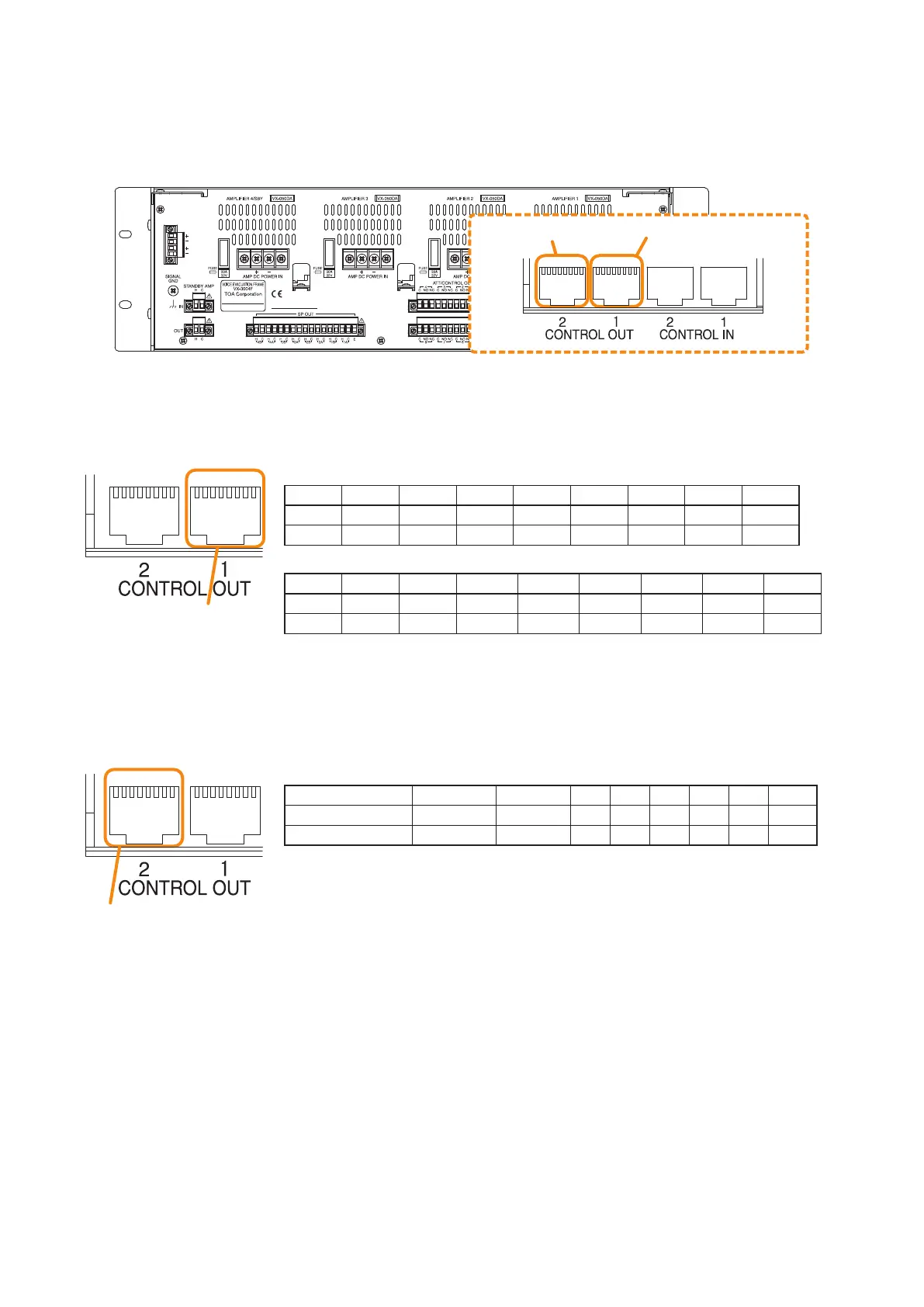
8.5. Control Output Terminal Connections
These terminals provide control outputs.
Control signals (make contact) are output in synchronization with unit operation.
The RJ45's pin arrangement and pin functions are shown below.
87654321 87654321
VX-3000F
Control output terminal 2 Control output terminal 1
Pin1 Pin2 Pin3 Pin4 Pin5 Pin6 Pin7 Pin8 Shield
GENERAL FAULT
CPU FAULT
CPU OFF NC NC NC NC NC Com
NO NO NO NO NO NO NO NO
-
• VX-3004F/3008F
Pin1 Pin2 Pin3 Pin4 Pin5 Pin6 Pin7 Pin8 Shield
CO_9 CO_10 CO_11 CO_12 CO_13 CO_14 CO_15 CO_16 Com
NO NO NO NO NO NO NO NO
-
• VX-3016F
Pin1 Pin2 Pin3 Pin4 Pin5 Pin6 Pin7 Pin8 Shield
CO_17 CO_18 CO_19 CO_20 CO_21 CO_22 CO_23 CO_24 Com
NO NO NO NO NO NO NO NO
-
Control output terminal 1
87654321 87654321
Control output terminal 2
87654321 87654321