2-16
Chapter 2
NOMENCLATURE AND FUNCTIONS
5. VX-3000CT CONTROL PANEL
• The VX-3000CT is a 1U size* Control panel mountable in an EIA standard equipment rack.
• Operation such as the activation of general broadcast and the input/output volume control can be performed
by connecting the VX-3000CT to the VX-3000F via network. Up to 2 VX-3000CT units can be connected to
a single VX-3000F unit.
• The VX-3000CT unit is equipped with 9 function keys and 8 volume controls, to each of which a function can
be assigned using the VX-3000 Setting Software.
* 1U size = 44.5 mm (standard size)
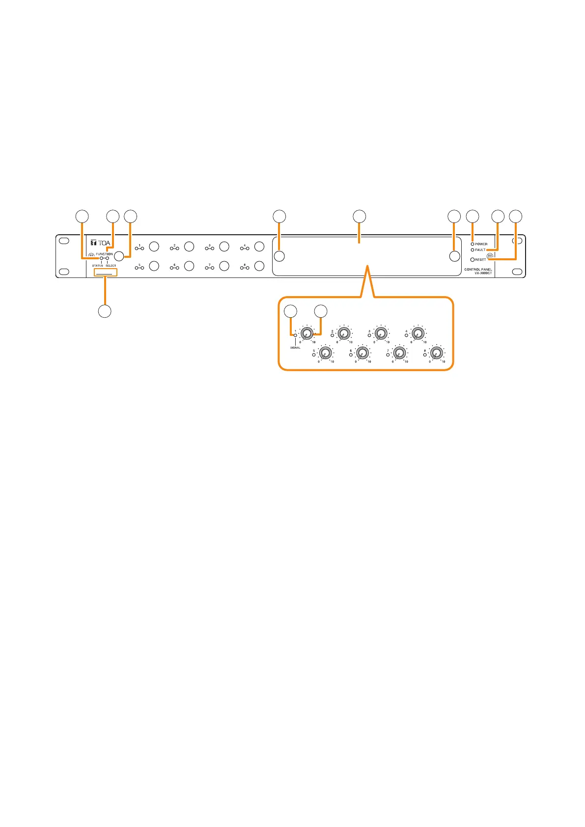
[Front]
(Inside of the cover)
12 3 5 564 7 8
9
10 11
1. Power indicator (Green)
Lights when power is being supplied.
2. Status indicator (Yellow/Green)
Lights yellow or green, or goes off in
synchronization with the operation state of the
function key.
(See the separate Operating Instructions,
"INDICATOR STATUS OF THE CONTROL
PANEL AND REMOTE MICROPHONES.")
3. Selection indicator (Green)
Lights or goes off in synchronization with the
operation state of the function key.
(See the separate Operating Instructions,
"INDICATOR STATUS OF THE CONTROL
PANEL AND REMOTE MICROPHONES.")
4. Function keys
Pressing a specic function key executes the
function that has been assigned to that key by
the VX-3000 Setting Software. Assignment of
functions to specic keys is done using the VX-
3000 Setting Software.
(See the separate Setting Software Instructions,
"VX-3000CT Setting.")
5. Volume control section cover knobs
The volume control section cover can be removed
by pulling the both knobs.
6. Volume control section cover
7. Fault indicator (Yellow)
Lights when an equipment error is detected.
8. Reset key
Resets the VX-3000CT when this key is pressed.
9. MAC address
This is the MAC address* for the unit. Since
the relationship of each unit location to its MAC
address is established when setting the network
attributes, keep track of this relationship for later
use.
* The unit’s MAC address consists of 12
hyphenated alphanumeric characters.
10. Signal indicator (Green)
Indicates the status of the input or output assigned
to the Volume control (11). If the indicator functions
as input signal indicator, it lights when the audio
level of the input channel assigned to the Volume
control (11) is –25 dB or more regardless of the
volume control value.
If the indicator functions as output signal indicator,
it lights when the audio level of the set individual
output zone is –25 dB or more.
The setting can be performed using the VX-3000
Setting Software.
(See the separate Setting Software Instructions,
"VX-3000CT Setting.")