3-57
Chapter 3
INSTALLATION AND SETTING PROCEDURES (HARDWARE)
8. CONNECTIONS
8.1. Removable Terminal Plug Connection
Notes
• Do not use a micro screwdriver. Sufcient torque is not given to the screws when tightening them, and
connections may not be secured.
• Avoid soldering stranded or shielded cable, as contact resistance may increase when the cable is tightened
and the solder is crushed, possibly resulting in an excessive rise in joint temperatures.
• When connecting 2 cables or a shielded cable to a single terminal, use a ferrule terminal with an insulation
sleeve to crimp the cables because such cable conductors could become loose.
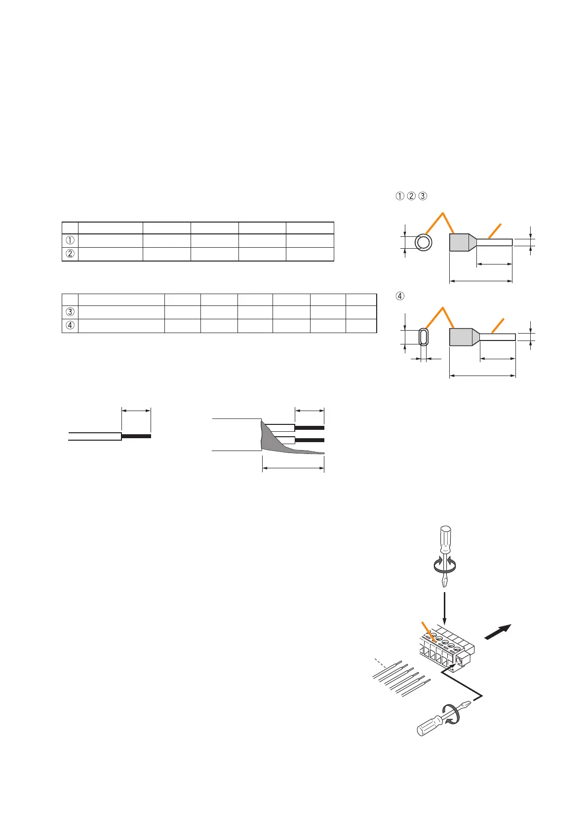
Recommended ferrule terminals for signal cables
(made by DINKLE ENTERPRISE)
Unit: mm
Model Number a b l1 l2
DN00308D 1.9 0.8 12 8
DN00508D 2.6 1 14 8
Recommended ferrule terminals for power supply cables
(made by DINKLE ENTERPRISE)
Unit: mm
Model Number a a1 a2 b l1 l2
DN01508D
3.5
- -
1.7 14 8
DN01508B
-
6.6 3.6 2.3 16 8
Crimping tool: DNT01-2206B (made by DINKLE ENTERPRISE)
[Cable sheath to trim]
Insulation sleeve
Contact section
Insulation sleeve
Contact section
a
l
2
a
1
a
2
l
1
l
2
l
1
bb
Solid cable and stranded cable
Shielded cable
7 mm*
7 mm*
15 mm
* Expose 8 mm or more when using the
above ferrule terminal, and cut off an extra
conductor protruding from the sleeve.
[Wiring procedures]
Procedures below are for the removable terminal plug with xing screws.
Step 1. Loosen the terminal screw and insert the
cable lead.
Step 2. Tighten the screw.
Pull on the cable lead to ensure it is securely
connected.
If the lead pulls out, loosen the screw and
follow the above procedures again.
Step 3. Insert the terminal plug into the corresponding
terminal block in the unit's rear panel.
Step 4. Tighten the xing screws.
Note
Do not reverse Steps 1 – 2 and 3 – 4 above. Force
is applied to the connected receptacle pins while
tightening the terminal screw and they may be
damaged, resulting in bad connector contact.
Removable
terminal plug
1
1
2
3
To Tighten To Loosen
Tighten
4