3-49
Chapter 3
INSTALLATION AND SETTING PROCEDURES (HARDWARE)
6.17. Installing the RM-500 on a Wall
[Mounting hardware]
To mount the RM-500 on the wall, the following parts are required.
Wall mounting bracket WB-RM500 ............................................. 1 (option)
4 x 25 tapping screw (for direct wall mounting) ........................... 2 (supplied with the WB-RM500)
M4 x 20 machine screw (for mounting to the switch box) ........... 2 (supplied with the WB-RM500)
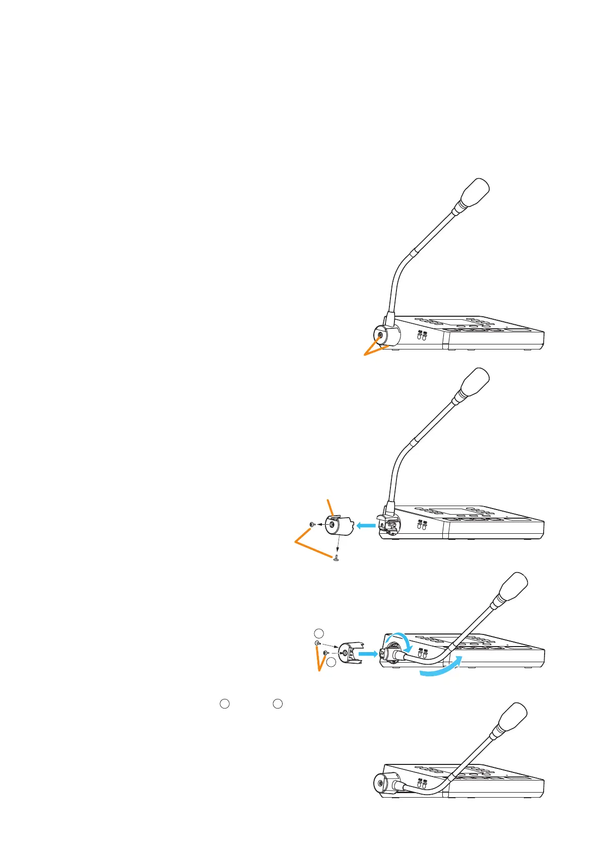
6.17.1. Changing the orientation of the microphone
The RM-500’s microphone is installed in the orientation
shown on the right gure by default.
When mounting the RM-500 on the wall, change the
orientation of the microphone following the procedure
below.
Screw
RM-500
Screw
Microphone fixing cover
1
2
4
3
Screws removed
in Step 1.
1
2
Step 1. Remove 2 screws securing the microphone,
then detach the microphone xing cover.
Step 2. Rotate the microphone 90° as shown at right.
Note
The microphone can be xed only at the
specied angle.
Be careful not to pinch the cable when
rotating it to avoid damage to the cable.
Doing otherwise may result in malfunction.
Step 3. Attach the microphone xing cover so that it
ts in place to x the microphone, then secure
the cover with 2 screws removed in Step 1.
Notes
• Be sure to install the screws
1
rst, then
2
in
the gure.
• When securing the cover, be sure to check
the screw holes and tighten the screws
correctly.
Step 4. Change the direction of the microphone for
an appropriate position.