2-26
Chapter 2
NOMENCLATURE AND FUNCTIONS
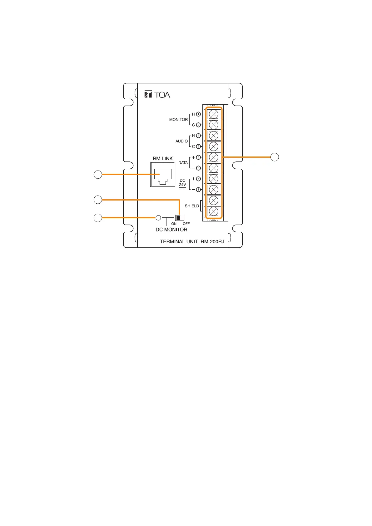
10. RM-200RJ TERMINAL UNIT
Convert the RJ45 connector into a screw terminal block. It is used to connect between a trunk cable (such as
CPEV cable) and a feeder cable (such as LAN cable) in wiring a remote microphone.
[Front]
1
2
3
4
1. RM link terminal
Connect to the RS link terminal of the VX-3000F or
RM link terminal of the RM-300X or RM-500.
2. Power monitor switch
Set to ON to enable the Power monitor indicator.
(Factory-preset: ON)
3. Power monitor indicator (Green)
Lights if the source voltage of the DC power input
exceeds the minimum operating voltage of the RM-
300X or RM-500 when the Power Monitor Switch is
set to ON.
4. Screw terminal block
The Screw terminal block and RM link terminal are
internally connected in parallel. Numbers 1 through
8 indicated beside each terminal correspond to the
pin numbers of the RJ45 connector to be connected
to the RM link terminal (1).
• Audio monitor terminals [MONITOR H/C]
Connect the audio monitor line from the VX-
3000F to the RM-300X.
• Audio output terminals [AUDIO H/C]
Connect the audio output line from the RM-300X
or RM-500 to the VX-3000F.
• RM communication terminals [DATA +/–]
Connect the control communication line between
the VX-3000F and the RM-300X or RM-500.
• DC power input terminals [DC 24 V +/–]
Used to supply DC power from the VX-3000F to
the RM-300X or RM-500.
• Shield terminals [SHIELD]
Connect the shield wires for noise reduction or
for system control.
Be sure to connect at least one shield wire.