3-22
Chapter 3
INSTALLATION AND SETTING PROCEDURES (HARDWARE)
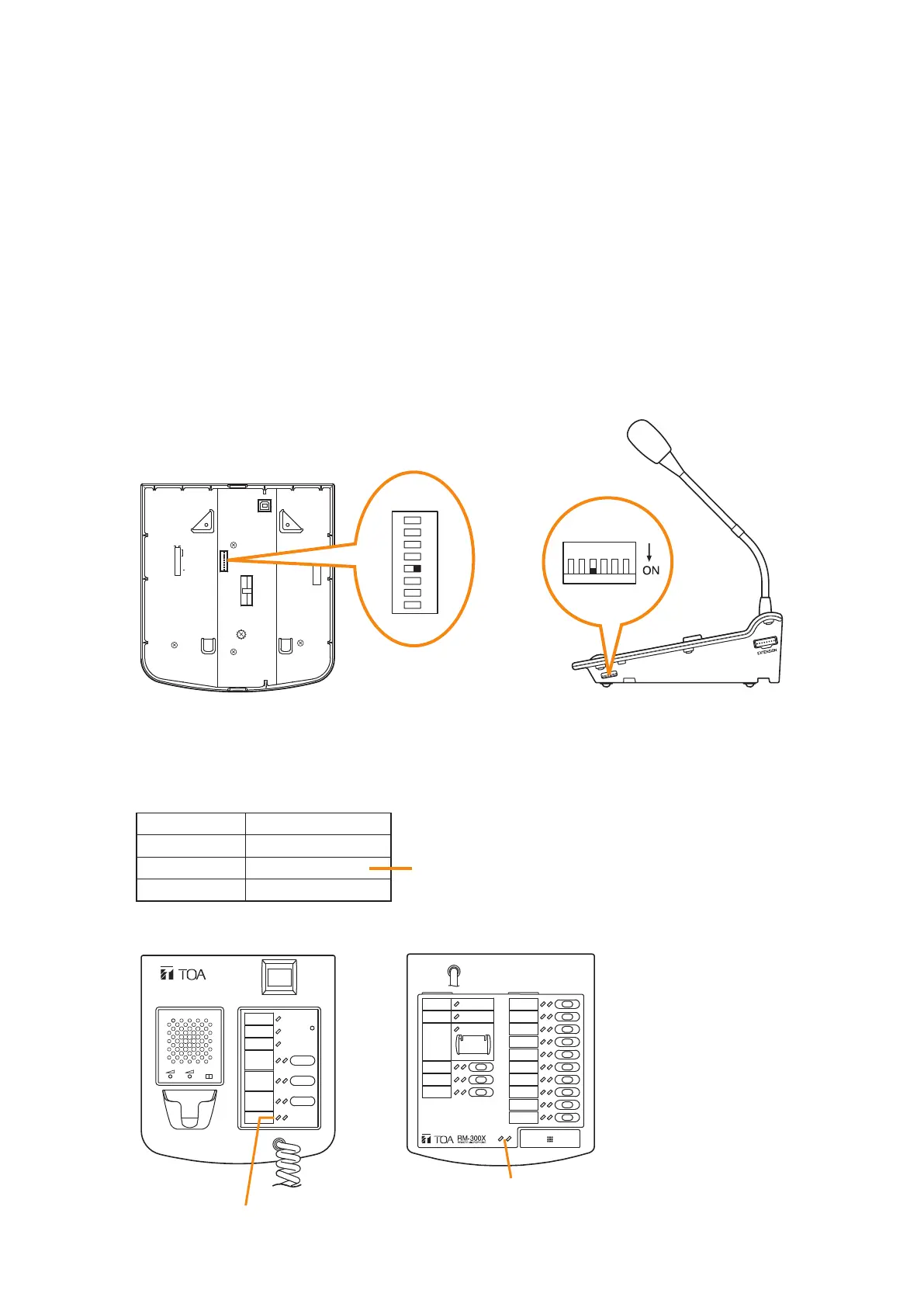
6.2. Adjusting Microphone Sensitivity
6.2.1. RM-200SF: Switch 5 operation or RM-300X: Switch 4 operation)
Since the DIP switch can be set to make the broadcast status indicator show output signal level,* adjust the
microphone sensitivity using the following procedure:
* When the microphone is in use, the indicator shows the output signal level. When the microphone is not in
use, it shows the broadcast status.
Step 1. Set switch 5 of the DIP switch on the rear panel of the RM-200SF to ON or switch 4 on the side panel
of the RM-300X to ON.
The broadcast status indicator on front panel of the RM-200SF or top panel of the RM-300X switches
to show the output signal level.
Note
Both switches are set to OFF by default.
8
7
6
5
4
3
2
1
TERMINATION
CPU OFF
LEVEL METER
COMMUNICATION
UNIT ID
OnOff
DIP SWITCH
RM-200SF rear RM-300X side
1
2
ON
3
4
5
6
7
8
123456
Step 2. Speak into the microphone.
The broadcast status indicator shows the microphone's output signal level.
The following table shows how the output level is shown.
Indicator Color
Lights red
Lights green
Off
Output Signal Level
Over 0 dB
–20 dB to 0 dB Appropriate level
Under –20 dB
RM-300X topRM-200SF front
RM-200SF
MIC SP CPU
OFF ON
Broadcast status indicator
Broadcast status indicator