2-3
Chapter 2
NOMENCLATURE AND FUNCTIONS
1. Power indicator (Green)
Lights when the power is supplied.
Flashes in standby state.
2. RUN indicator (Green)
Normally ashes continuously. Goes off while in
a CPU off state (p. 3-30). Also goes off while in
standby state*
1
.
*
1
A state during power failures or a state that the
unit is internally initialized after power-on
3. Emergency indicator (Red)
Lights when the VX-3000 system is in an
emergency condition or while in a CPU off state
(p. 3-30).
4. CPU off indicator (Red)
Lights while in a CPU off state (p. 3-30).
5. LAN A indicator (Green)
Lights when the LAN link A connector (49) on the
rear panel is connected, and ashes during LAN
communications.
6. LAN B indicator (Green)
Lights when the LAN link B connector (49) on the
rear panel is connected, and ashes during LAN
communications.
7. RS link A indicator (Green)
Lights when the RS link A connector (50) on
the rear panel is connected, and ashes while
communications are being performed via the RS
link A connector.
8. RS link B indicator (Green)
Lights when the RS link B connector (50) on
the rear panel is connected, and ashes while
communications are being performed via the RS
link B connector.
9.Amplierpeakindicators(Red)
Show the input signal state to the power amplier
when the module is installed.
The indicator corresponding to the module slot
port will light if the input signal level exceeds +0.5
dB*
2
.
It remains unlit when no module is installed.
10.Ampliersignalindicators(Green)
Show the input signal state to the power amplier
when the module is installed.
The indicator corresponding to the module slot
port will light if the input signal level exceeds
-
25
dB*
2
.
It remains unlit when no module is installed.
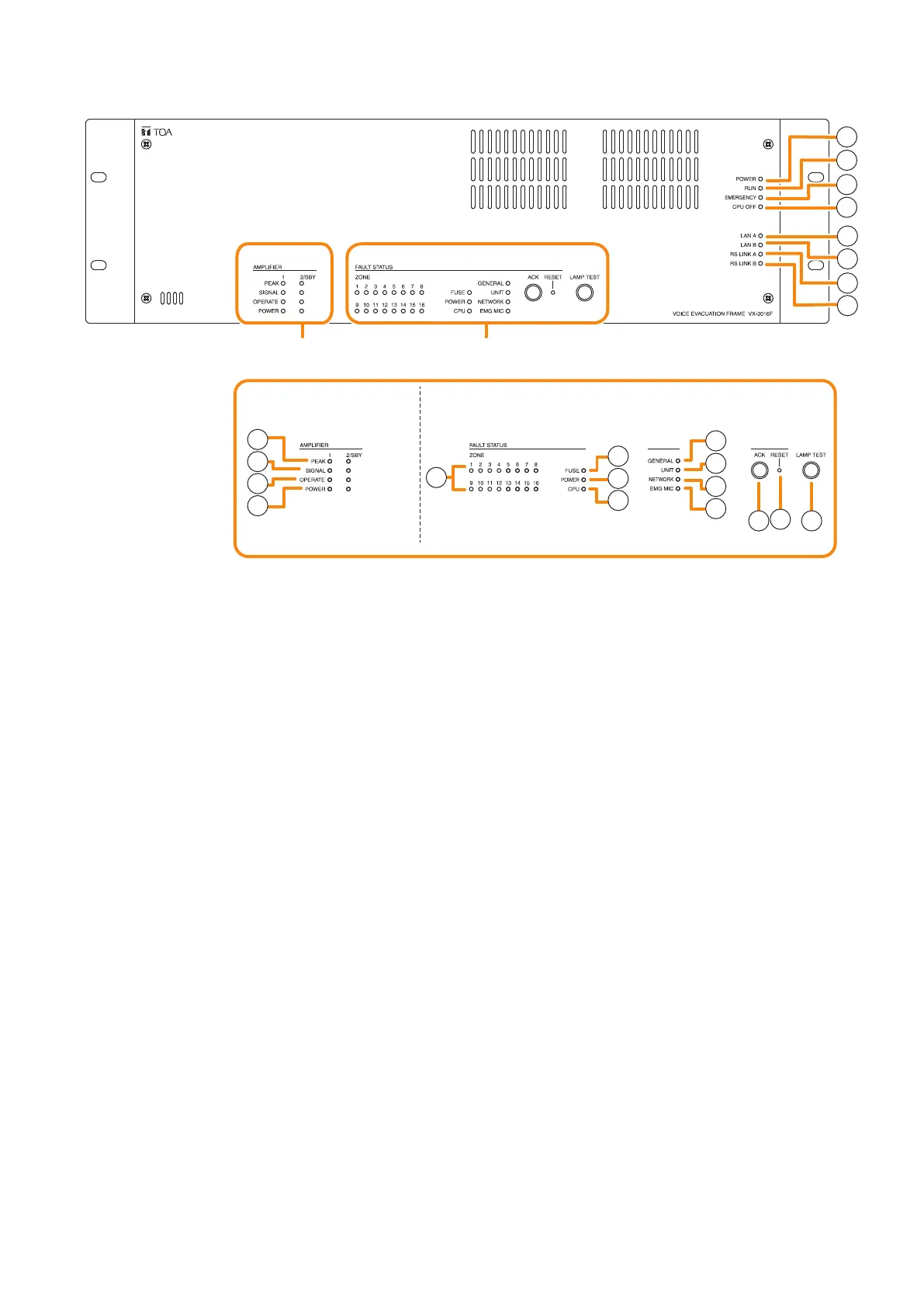
VX-3016F
[Amplifier section] [Fault status section]
9
10
11
12
13
14
15
16
17
18
19
20
21
22
23
1
2
3
5
6
7
8
4
Amplifier section Fault status section
*
2
0 dB = 1 V