3-8
Chapter 3
INSTALLATION AND SETTING PROCEDURES (HARDWARE)
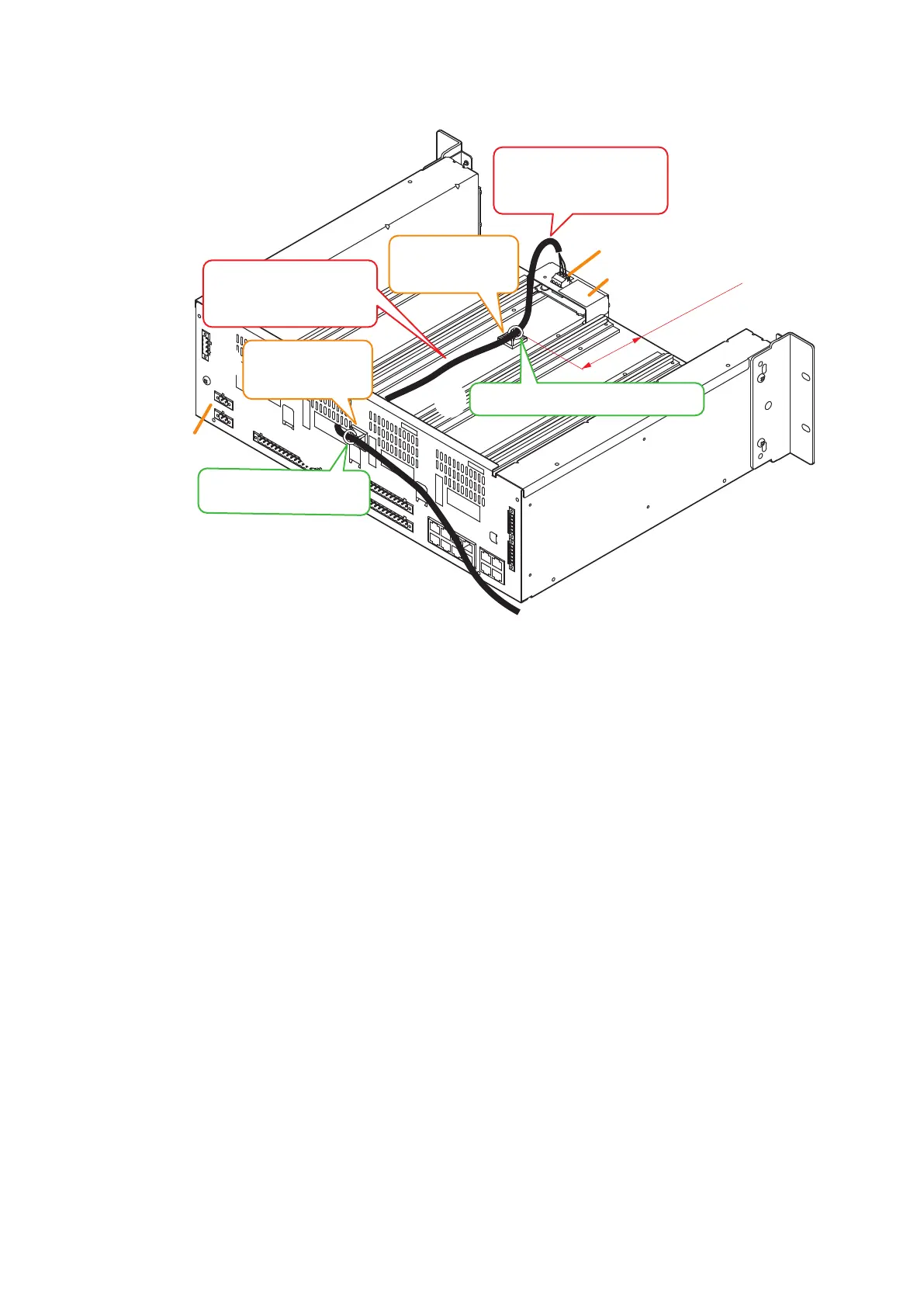
Step 5. Attach each of the mount bases supplied with the Line output module to 2 places. (See the gure
below.)
Step 6. Connect the cable to the 3-pin removable terminal plug supplied with Line output module, then attach
the terminal plug to the module.
See p. 3-57 for connection of the removable terminal plug.
Step 7. Extract the cable from the cable exit opening in the VX-3000F's rear panel, then secure it to the mount
base with the cable tie.
Notes
• Do not allow the cable to protrude outward from the VX-3000F’s frame unit and from between the
rails on both sides.
• Do not allow the cable pulled out from the opening in the rear panel of the VX-3000F’s frame to
contact with a sharp edge.
Step 8. Replace the front panel.
Secure it using 4 xing screws for front panel removed in Step 2.
VX-300LO
Removable terminal plug
(3P, supplied with the VX-300LO)
VX-3000F
rear
80 mm
Secure the cable with the cable tie.
Mount base*
2
(supplied with the
VX-300LO)
Mount base
*1
(supplied with the
VX-300LO)
*
2
*
3
5
5
6
7
7
Attach the mount base near
the center between the rails.
Do not allow the cable to
protrude from the frame
unit.
Do not allow the cable to
protrude from the frame
unit.
*
1
Secure the cable with the
cable tie.
*
3
Attach the mount base so as not to
block the slots in the frame.
Secure the cable so as not to contact
with the frame edge.