3-41
Chapter 3
INSTALLATION AND SETTING PROCEDURES (HARDWARE)
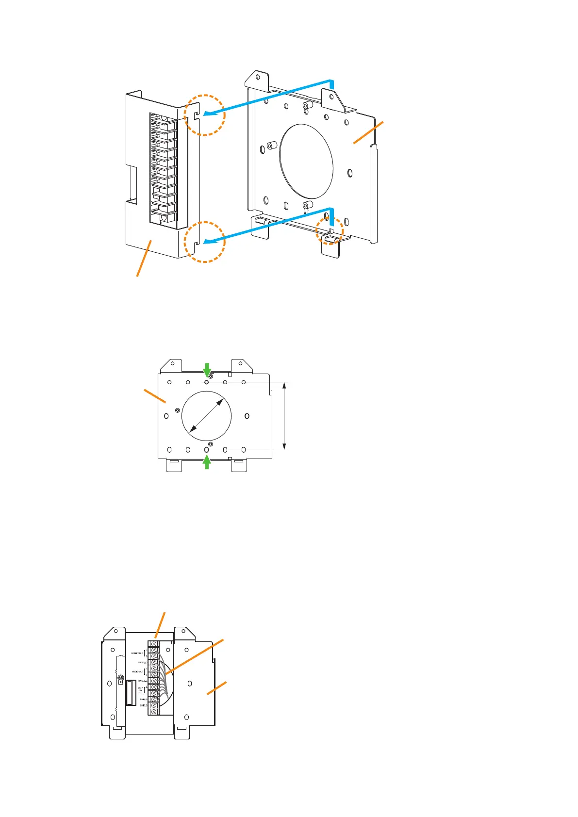
(2) Slide the Bracket A as show below to detach it from the Bracket B.
(3) Attach the Bracket B to the electrical box using 2 screws M3.5 x 20 supplied with the RM-200SF.
(4) Replace the Bracket A.
Reverse the procedures (1) and (2) above.
Note
Take care not to pinch the routed link cable between the Brackets A and B.
Bracket A
Bracket B
Slide the Bracket A upward, then pull it toward you.
Screw holes for mounting to
the electrical box (2 places)
Unit: mm
Bracket B
83.5
ø60
Step 2. Connect the link cable to the screw terminal block.
Wall mount bracket unit
(supplied with the RM-200SF)
Link cable
Bracket A
Bracket B
Note
Put the link cable inside the Bracket A after connection
completion.
Do not allow the link cable to protrude.
The cable may be damaged if it protrudes when the
bracket unit is installed onto the wall.