Chapter 2 – Implement Setup
9
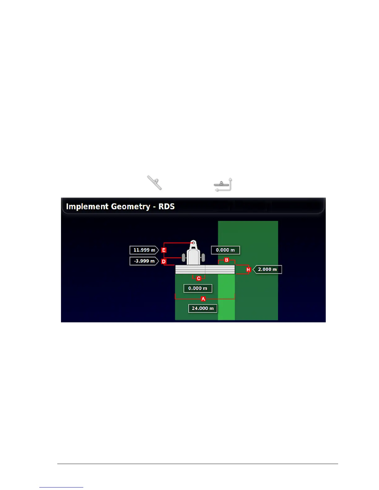
2.3. Setting implement geometry
Sets the implement measurements so that guidance can work accurately.
Note: Measure the implement dimensions as accurately as possible.
The recommended tolerance is +/- 5 cm.
When an ISOBUS implement is connected, some of the geometry items
are provided by the implement and cannot be altered in the console user
interface. Any changes to these must be made in the Athene ISOBUS
UT control screen (see Setting up working width, page 32).
To set the implement geometry:
1.
Select Implement / Geometry .
2. Select an implement dimension. The name of the dimension
appears in the title bar.
Dimensions requested vary according to the type of implement
selected.
3. Add or adjust dimensions where needed and confirm.
Measurements used are as follows:
l Swath Width: Measures the working width of the implement (that
is, the width of the area that is treated during one pass of the
implement).