Product Overview
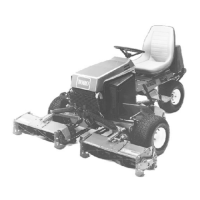
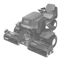
Figure 15
1. Operator’s seat
4. Rear cutting units
2. Rollover protection system
(ROPS), along with the seat
belt
5. Air cleaner
3. Front cutting units
6. Engine hood
Controls
Seat Controls
T he seat adjusting lev er ( Figure 16 ) allo ws y ou
to adjust the seat 4 inc hes fore and aft. T he seat
adjusting knob ( Figure 16 ) adjusts the seat for the
operator’ s w eight. T o adjust the seat fore and aft,
pull the lev er on the left side of the seat assembly
outw ard. After mo ving the seat to the desired
location, release the lev er to loc k the seat into
position. T o adjust for the operator’ s w eight, tur n
the spring tension knob cloc kwise to increase
tension or countercloc kwise to decrease tension.
Figure 16
1. Seat adjusting lever 2. Seat adjusting knob
Traction Pedal
T he traction pedal ( Figure 17 ) controls forw ard
and rev erse operation. Press the top of the
pedal to mo v e forw ard and the bottom to mo v e
rearw ard. Ground speed de pends on ho w far y ou
press the pedal. F or no load, maxim um g round
speed, fully press the pedal while the throttle is in
the F ast position.
T o stop , reduce foot pressure on the traction pedal
and allo w it to retur n to the center position.
Figure 17
1. Traction pedal
Traction Speed Limiter
Preset this lev er ( Figure 18 ) to limit the amount
the traction pedal can be pressed in the forw ard
direction to maintain a constant mo wing speed.
22

 Loading...