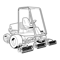
Figure 73
1. Test port #1
2. Test port #2
Cutting Unit System
Maintenance
Adjusting the Cutting Unit
Lift Rate
T he cutting unit lift circuit is equipped with 3
adjustable v alv es used to ensure that the cutting
units do not raise too quic kly and bang ag ainst
the lift stops . Adjust the cutting unit lift rate as
follo ws:
Adjusting the Center Cutting Unit
1. Locate the v alv e behind the access panel abo v e
the operator’ s platfor m ( Figure 74 ).
Figure 74
1. Center cutting unit adjustment valve
2. Loosen the setscrew on the v alv e and rotate
the v alv e appro ximately 1/2 tur n cloc kwise .
3. V erify the lift rate adjustment b y raising and
lo w ering the cutting unit sev eral times . Adjust
as required.
4. After attaining the desired lift rate , tighten the
setscrew to loc k the adjustment.
Adjusting the Outside Front Cutting
Units
1. Locate the v alv e on the flo w di vider (under the
foot rest) ( Figure 75 ).
Figure 75
1. Outside front cutting units adjustment valve
56

 Loading...


