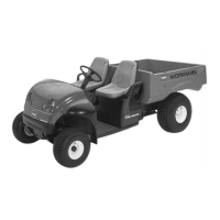
Figure3
1.Cover4.Steeringwheel
2.Nut
5.Steeringshaft
3.Washer(5/8inch)
2
InstallingtheROPS
Partsneededforthisprocedure:
1
ROPSframe
6
Flange-headbolt(1/2x1-1/4inch)
Procedure
1.Applymedium-grade(service-removable)thread
lockingcompoundtothethreadsofthe6ange-head
bolts(1/2x1-1/4inch).
2.AligneachsideoftheROPSwiththemountingholes
oneachsideofframeofthemachineasshownin
Figure4.
Figure4
1.ROPSmountingbracket
2.Flange-headbolt
3.SecureeachsideoftheROPSmountingbracketto
frameofthemachinewith3ange-headbolt(1/2x
1-1/4inch).
4.Torquetheange-headboltsto115N-m(85ft-lb).
3
ConnectingtheBattery(TC
andHModelsonly)
NoPartsRequired
Procedure
WARNING
Incorrectbatterycableroutingcoulddamagethe
machineandcablescausingsparks.Sparkscan
causethebatterygassestoexplode,resultingin
personalinjury.
•Alwaysdisconnectthenegative(black)battery
cablebeforedisconnectingthepositive(red)
cable.
•Alwaysconnectthepositive(red)batterycable
rst.
1.Squeezethebatterycovertoreleasethetabsfromthe
batterybase(Figure5).
13
 Loading...
