g025881
Figure47
1.Flangedbolt
5.Negative(-)battery
terminal
2.Terminalcover
(black—negativebattery
terminal)
6.Flangednut
3.Terminalcover
(red—positivebattery
terminal)
7.Batterytray
4.Positive(+)battery
terminal
8.Batterystrap
4.Disconnectthenegativebatterycablefromthe
negative(-)batteryterminal,andremovethe
cablefromthebattery(Figure47).
5.Slidetheredterminalcoveroffthepositive
batteryterminal(Figure47).
6.Disconnectthepositive(red)batterycable,and
removethecablefromthebattery(Figure47).
7.Removethehookofthebatterystrapfromthe
batterytray(Figure47),andremovethebattery.
InstallingtheBattery
1.Placethebatteryontothemachine(Figure47).
2.Securethebatterytothebatterytraywiththe
batterystrap.
3.Installthepositive(red)batterycabletopositive
(+)batteryterminalwithaangedboltand
angednut(Figure47).
4.Slidetheredterminalcoveroverthe
positive-batteryterminal.
5.Installthenegativebatterycableandtheground
wiretothenegative(-)batteryterminalwitha
angedboltandangednut(Figure47).
6.Slidetheblackterminalcoveroverthe
negative-batteryterminal.
ChargingtheBattery
WARNING
Chargingthebatteryproducesgassesthat
canexplode.
Neversmokenearthebatteryandkeepsparks
andamesawayfromthebattery.
Important:Alwayskeepthebatteryfullycharged
(1.265specicgravity)topreventbatterydamage
whenthetemperatureisbelow0°C(32°F).
1.Removethebatteryfromthechassis;referto
RemovingtheBattery(page43).
2.Checktheelectrolytelevel.
3.Ensurethatthellercapsareinstalledonthe
battery.
4.Chargethebatteryfor1hourat25to30Aor6
hoursat4to6A.
5.Whenthebatteryisfullycharged,unplugthe
chargerfromtheelectricaloutlet,anddisconnect
thechargerleadsfromthebatteryposts(Figure
48).
6.Installthebatteryontothemachineandconnect
thebatterycables;refertoInstallingtheBattery
(page44).
Note:Donotrunthemachinewiththebattery
disconnected;electricaldamagemayoccur.
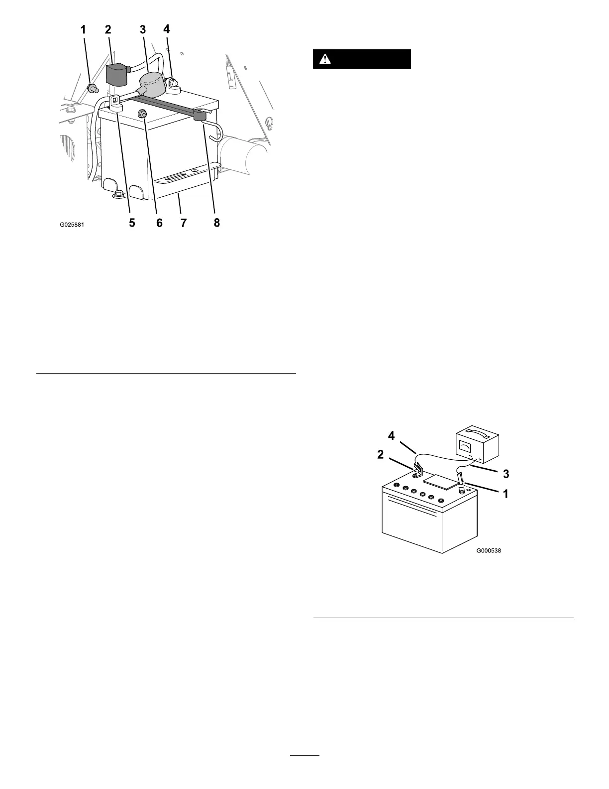
g000538
Figure48
1.Positivebatterypost
3.Red(+)chargerlead
2.Negativebatterypost
4.Black(-)chargerlead
JumpStartingaDischarged
Battery
ThefollowinginstructionsareadaptedfromtheSAE
J1494Rev.Dec.2001–BatteryBoosterCables
–SurfaceVehicleRecommendedPractice(SAE–
SocietyofAutomotiveEngineers).
44