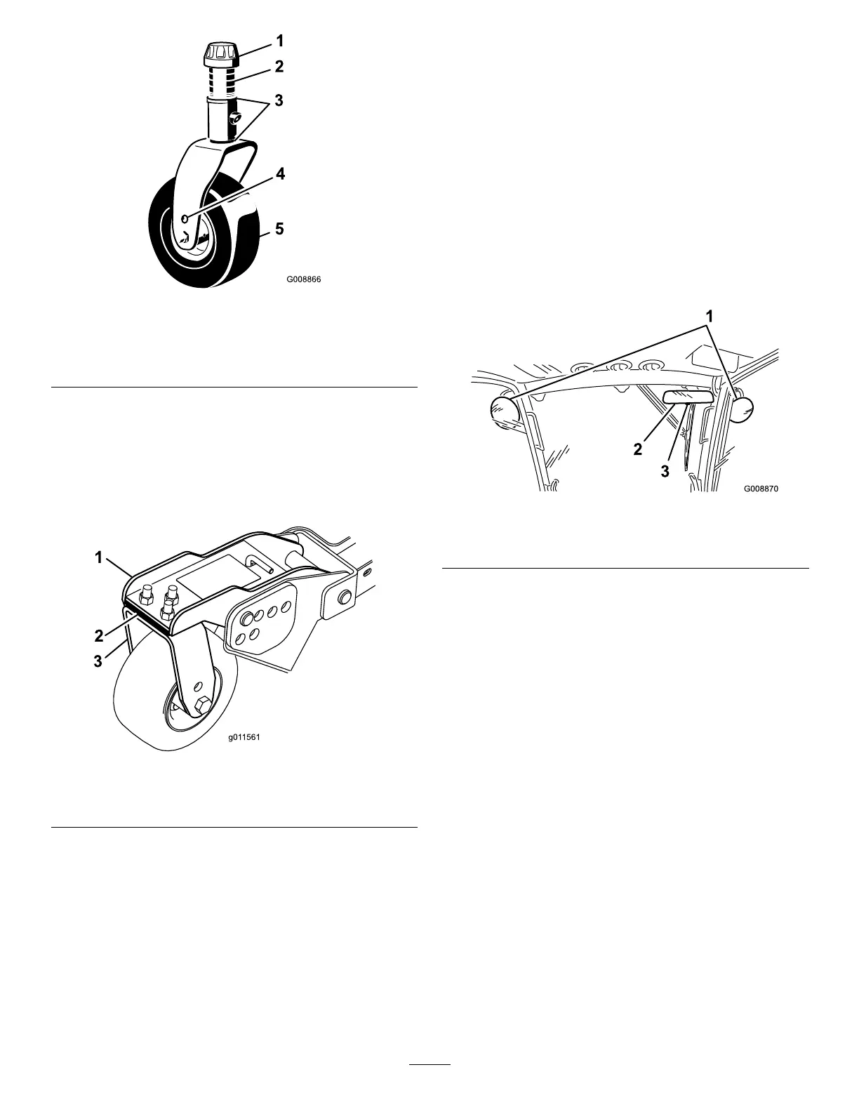
Figure28
1.T ensioningcap4.T opaxlemountinghole
2.Spacers5.Castorwheel
3.Shims
WingCuttingUnitSetup
Rotatebladeofeachspindleuntiltheendsfaceforwardand
backward.Measurefromtheoortothefronttipofthe
cuttingedge.Adjust1/8inchshimsonfrontcastorarm(s)
tomatchheightofcuttodecal(
Figure29).Fortheoutside
bladespindleonly,refertoAdjustingtheCuttingUnitPitch.
Figure29
1.Castorarm3.Castorfork
2.Shims
MatchingHeightOfCutBetweenCuttingUnits
1.Positionbladesidetosideonoutsidespindleofboth
wingcuttingunits.Measurefromtheoortothetip
ofthecuttingedgeonbothunitsandcompare.These
numbersshouldbewithin1/8inch(3mm)ofeach
other.
2.Addorremove1/8inchshimsasneededonwing
castorwheels.Recheckmeasurementbetweenoutside
edgesofbothwingcuttingunitsandadjustasnecessary.
AdjustingtheMirrors
Model30447only
RearViewMirror
Whilesittingintheseat,adjusttherearviewmirror
(Figure30)toattainthebestviewouttherearwindow.Pull
theleverrearwardtotiltthemirrortoreducethebrightness
andglareoflight.
SideViewMirrors
Whilesittingintheseat,haveahelperadjustthesideview
mirrors(Figure30)toattainthebestviewaroundthesideof
themachine.
Figure30
1.Sideviewmirrors
3.Lever
2.Rearviewmirror
AimingtheHeadlights
1.Loosenthemountingnutsandpositioneachheadlight
sothatitpointsstraightahead.Tightenthemounting
nutjustenoughtoholdtheheadlightinposition.
2.Placeaatpieceofsheetmetaloverthefaceofthe
headlight.
3.Mountamagneticprotractorontotheplate.While
holdingtheassemblyinplace,carefullytilttheheadlight
downward3degrees,thentightenthenut.
4.Repeattheprocedureontheotherheadlight.
StartingandStoppingthe
Engine
Important:Thefuelsystemwillautomaticallybleed
itselfwhenanyofthefollowingsituationsoccur:
•Initialstartupofanewmachine.
•Theenginehasceasedrunningduetolackoffuel.
•Maintenancehasbeenperformeduponthefuelsystem
components.
RefertotheBleedingAirfromtheInjectors.
26