ProductOverview
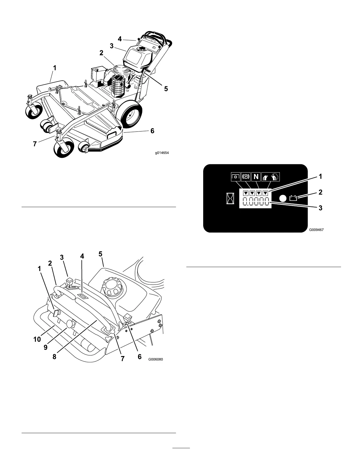
Figure4
1.Side-dischargechute
5.Parkingbrake
2.Engine6.Mowerdeck
3.Gastank
7.Frontcasterwheel
4.Controls
Controls
Becomefamiliarwithallthecontrols(Figure5)beforeyou
starttheengineandoperatethemachine.
Figure5
1.Ignitionswitch
6.Choke
2.Leftmotion-controllever7.Neutral-lockpositionfor
rightmotion-controllever
3.Throttlecontrol8.Rightmotion-controllever
4.Hourmeter9.Blade-controlswitch
(PTO)
5.Fueltank
10.OperatorManualtube
HourMeter
Thehourmeterrecordsthenumberofhourstheenginehas
operated.Itoperateswhentheengineisrunning.Usethese
timesforschedulingregularmaintenance(Figure6).
Safety-InterlockIndicators
Therearesymbolsonthehourmeterandindicatewitha
blacktrianglethattheinterlockcomponentisinthecorrect
position(Figure6).
Battery-IndicatorLight
WhentheignitionkeyisinitiallyturnedtotheOnposition,
thebatteryvoltagewillbedisplayedintheareawherethe
hoursarenormallydisplayed.
Thebatterylightturnsonwhentheignitionisturnedonand
whenthechargeisbelowthecorrectoperatinglevel(Figure
6).
Figure6
1.Safety-interlocksymbols
3.Hourmeter
2.Batterylight
ThrottleControl
Thethrottlecontrolhas2positions:FastandSlow.
Choke
Usethechoketostartacoldengine.
Blade-ControlSwitch(PTO)
Theblade-controlswitch(PTO)isusedtoengagethe
electricclutchtodrivethemowerbladeswiththerightside
motion-controlleverinthecenter,unlockedposition.Pull
theswitchuptoengagethebladesandrelease.Todisengage
theblades,pushtheblade-controlswitch(PTO)downor
moveorreleasetherightsidemotion-controlleverintothe
Neutral-Lockposition.
IgnitionSwitch
Thisswitchisusedtostartthemowerengineandhas3
positions:Start,Run,andOff.
13