g001455
Figure16
1.Axle-pivotbolt2.Axle-adjustmentbolt
4.Placeajackundertherearcenteroftheengine
frame.Raisetherearendoftheengineframe
upenoughtoremovethefront2axle-adjustment
bolts(Figure16).
Note:Usejackstandstosupportthemachine.
5.Raiseorlowertheengineframewiththejackso
thatyoucaninstallthefront2axle-adjustment
boltsinthedesiredholelocation(Figure16).
Note:Useataperedpunchtohelpalignthe
holes.
6.Tightenall4boltsandlowerthemachine.
7.Adjustthecontrolrodsandbrakelinkagesas
required;refertoAdjustingtheControlRods
(page21)andAdjustingtheParkingBrake
(page34).
Important:Youmustadjustthecontrolrods
andbrakelinkagewhenyouchangethe
axlepositionsforpropertractionandbrake
function.
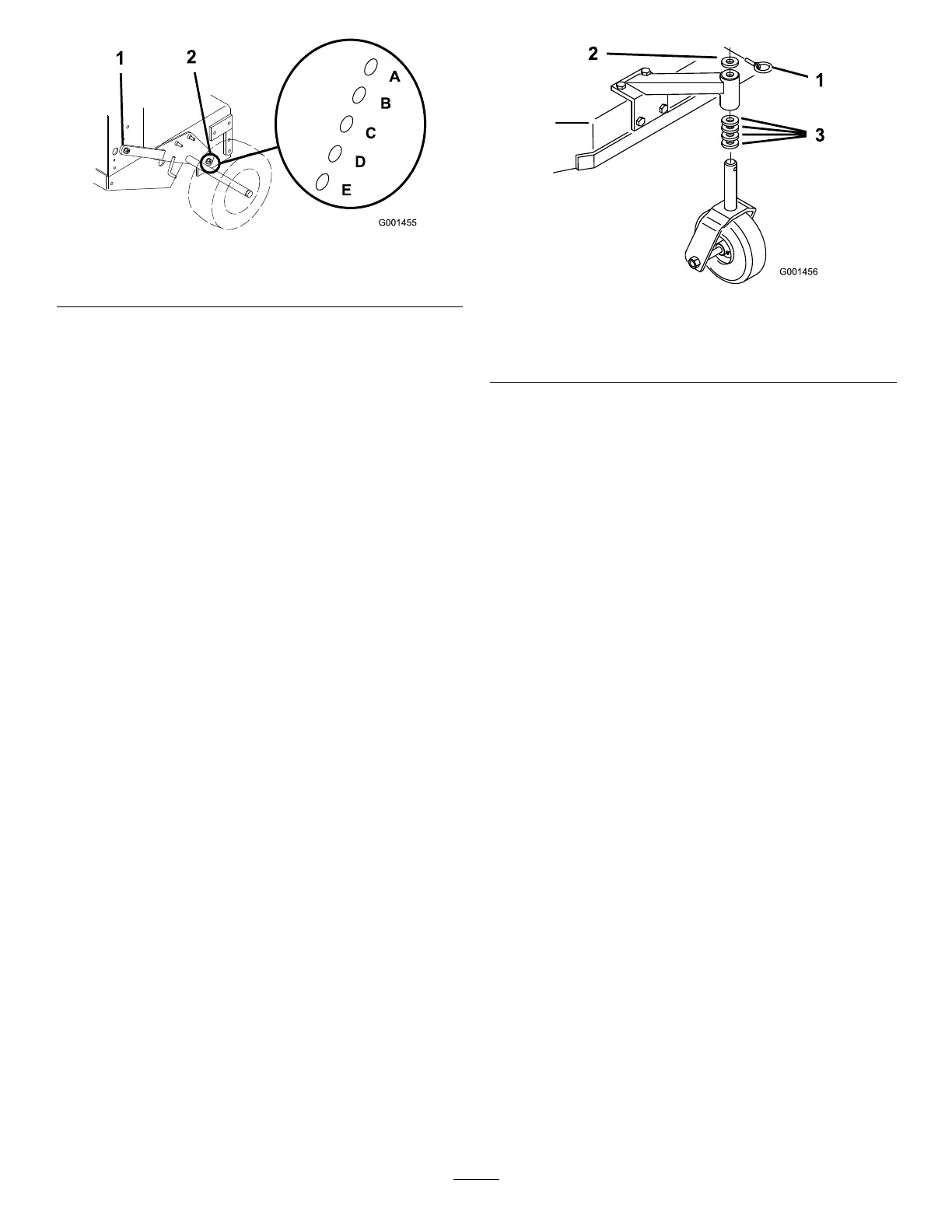
AdjustingtheCasterPosition
1.UsingtheHeight-of-CutChart(page22),adjust
thecasterspacerstomatchwiththeaxlehole
selected(Figure17).
g001456
Figure17
1.Latchpin
3.Spacer(13mmor1/2inch)
2.Spacer(5mmor3/16inch)
2.Removethelatchpin,slidethecasterfromthe
support,andchangethespacers(Figure17).
3.Installthecasterinthesupportandinsertthe
latchpin(Figure17).
20