g001563
Figure50
1.Measurefromthecuttingedgetoalevelsurface.
3.Rotatetheoppositeendsofthebladesforward.
4.Measurefromalevelsurfacetothecuttingedge
ofthebladesatthesamepositionasinstep1.
Note:Thedifferencebetweenthedimensions
obtainedinsteps1and2mustnotexceed3mm
(1/8inch).Ifthisdimensionexceeds3mm(1/8
inch),thebladeisbentandmustbereplaced;
refertoRemovingtheBlades(page41)and
InstallingtheBlades(page42).
RemovingtheBlades
Replacethebladesifyouhitasolidobjectorifthe
bladesareoutofbalanceorbent.Toensureoptimum
performanceandcontinuedsafetyconformanceof
themachine,usegenuineTororeplacementblades.
Replacementbladesmadebyothermanufacturers
mayresultinnon-conformancewithsafetystandards.
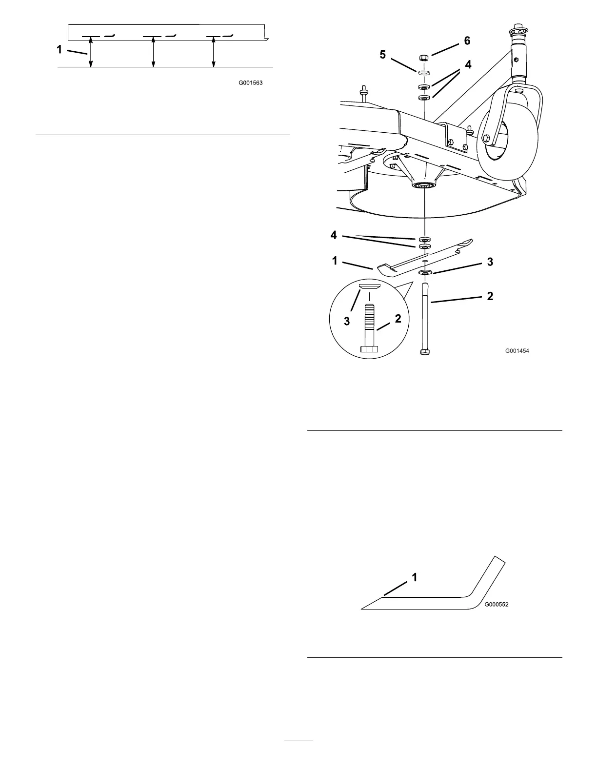
1.Holdthebladeboltwithawrench.
2.Removethenut,bladebolt,curvedwasher,
blade,spacers,andthinwasherfromthespindle
(Figure51).
g001454
Figure51
1.Blade
4.Spacer
2.Bladebolt5.Thinwasher
3.Curvedwasher
6.Nut
SharpeningtheBlades
1.Usealetosharpenthecuttingedgeatboth
endsoftheblade(Figure52).
Note:Maintaintheoriginalangle.
Note:Thebladeretainsitsbalanceifthesame
amountofmaterialisremovedfrombothcutting
edges.
g000552
Figure52
1.Sharpenatoriginalangle.
2.Checkthebalanceofthebladebyputtingitona
bladebalancer(Figure53).
Note:Ifthebladestaysinahorizontalposition,
thebladeisbalancedandcanbeused.
41