Refer to the Software Guide for more information.
g231075
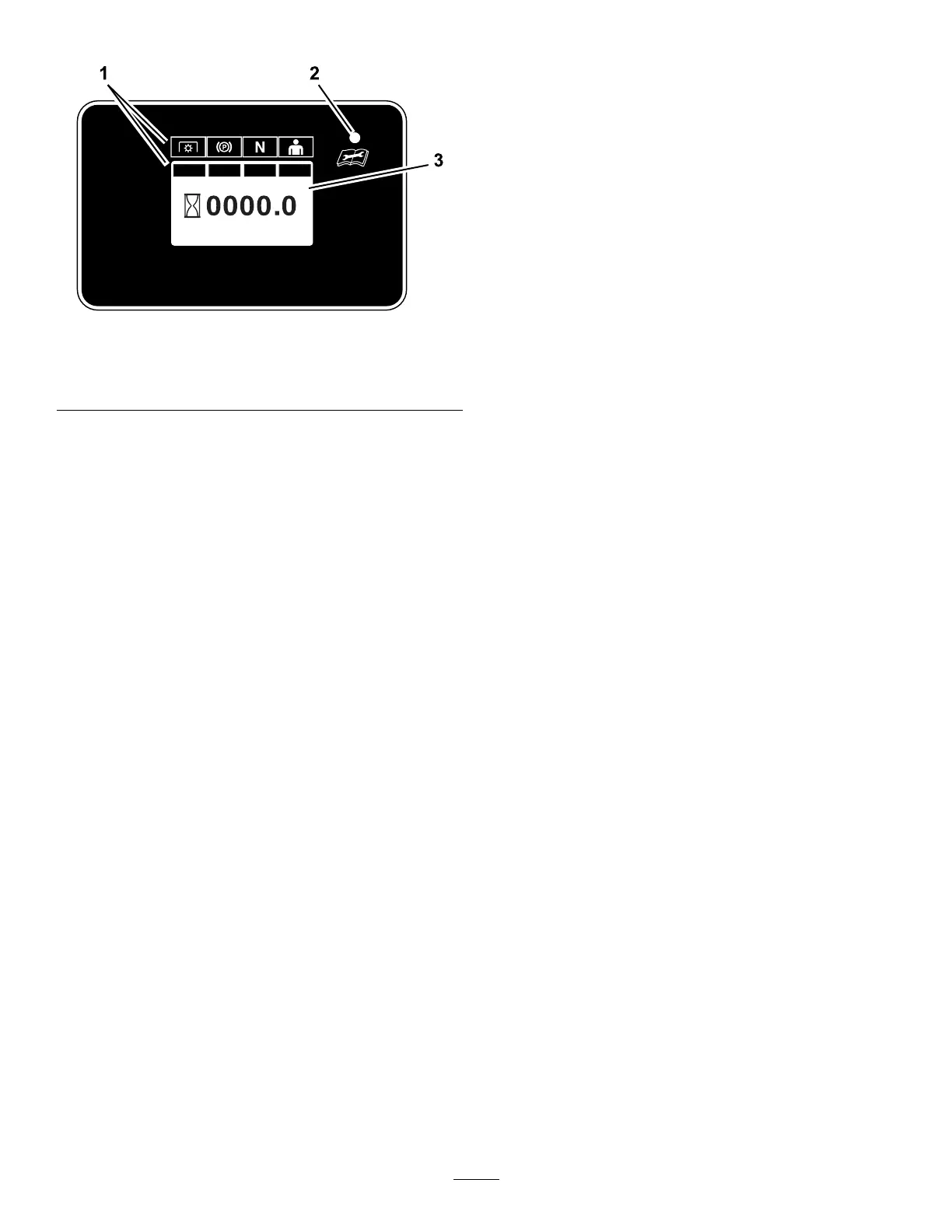
Figure 6
1. Safety-interlock indicators 3. Information screen
2. LED status light
LED Status Light
The LED is multi-colored to indicate the system status
and is located on the right side of the panel.
• Solid Green —indicates normal operating activity .
• Blinking Red —indicates a fault is active.
• Blinking Green and Orange —indicates a clutch
reset is required.
• Solid Red —indicates maintenance is required.
Refer to the Software Guide for more information.
Fuel Gauge
When the fuel-tank level is low , the LED status light
ashes a red light and the fuel-level symbol on the
screen ashes.
Refer to the Software Guide for more information.
Safety-Interlock Indicators
There are symbols on the hour meter that indicate with
a black bar that the interlock component is positioned
correctly ( Figure 6 ).
Motion-Control Levers
Use the motion-control levers to drive the machine
forward, reverse, and turn either direction ( Figure 4 ).
Neutral-Lock Position
Move the motion-control levers outward from the
center to the N EUTRAL - LOCK position when exiting
the machine ( Figure 27 ). Always position the
motion-control levers into the N EUTRAL - LOCK position
when you stop the machine or leave it unattended.
Parking-Brake Lever
Whenever you shut of f the engine, engage the parking
brake to prevent accidental movement of the machine.
Fuel-Shutoff V alve
Close the fuel-shutof f valve when transporting or
storing the machine; refer to Using the Fuel-Shutof f
V alve ( page 37 ) .
16