1. Park the machine on a level surface, disengage
the blade-control switch (PT O), and engage the
parking brake.
2. Shut of f the engine, remove the key , and wait
for all moving parts to stop before leaving the
operating position.
3. Using an air compressor , blow out any debris
from under the brake pole and around the brake
spacers ( Figure 79 ).
g010868
Figure 79
4. Check the condition of the wire-harness leads,
connectors, and terminals.
Note: Clean or repair as necessary .
5. V erify that 12 V is present at the clutch connector
when the blade-control switch (PT O) switch is
engaged.
6. Measure the gap between the rotor and
armature. If the gap is greater than 1 mm (0.04
inch), do the following steps:
A. Loosen both brake-mounting bolts 1/2 to 1
full turn as shown in Figure 80 .
Note: Do not remove the brake pole from
the eld shell/armature. The brake pole
has worn to match the armature and needs
to continue to match after you remove the
shim to ensure proper brake torque.
g010870
Figure 80
1. Brake-mounting bolt
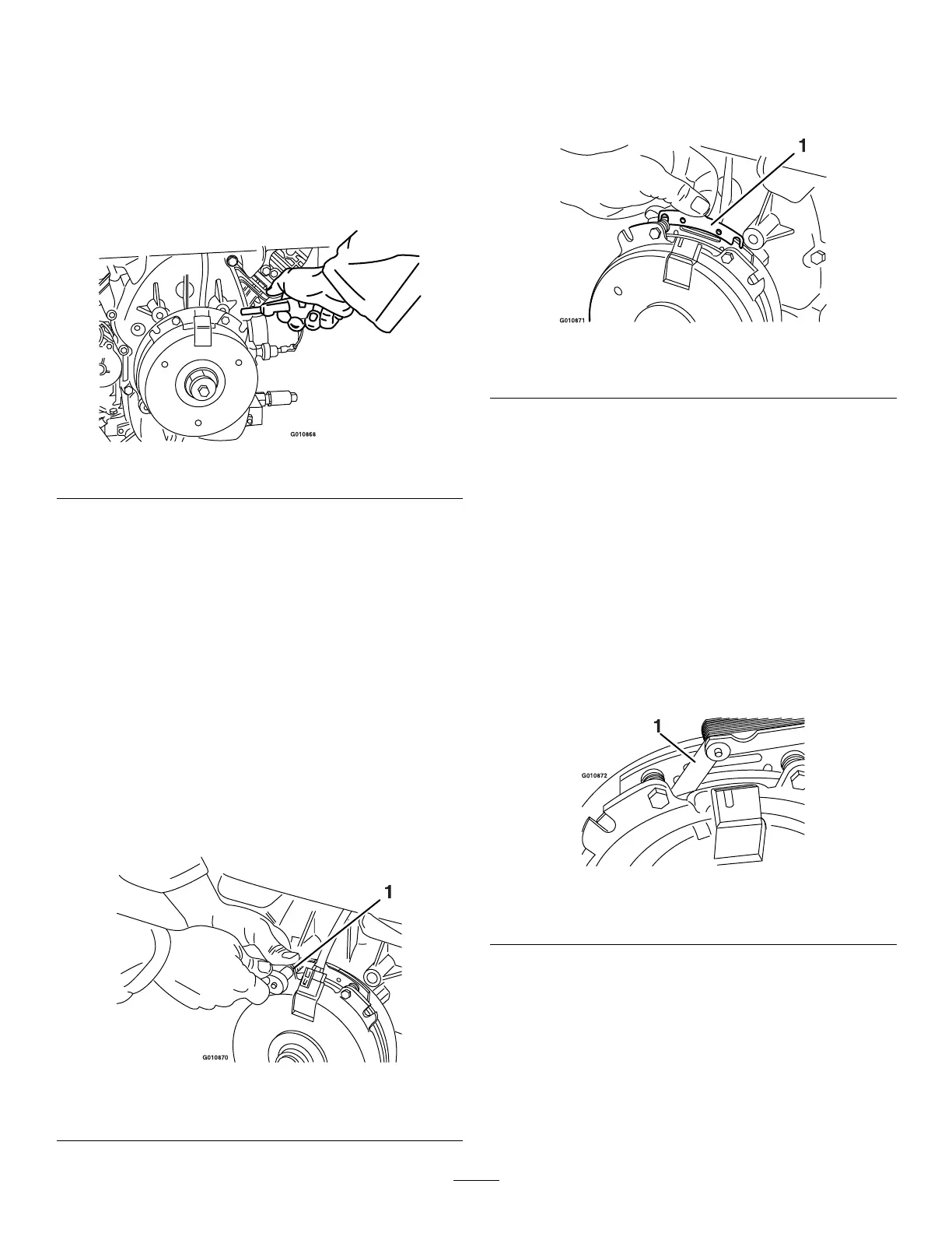
B. Using needle-nose pliers, or by hand, hold
the tab and remove the shim ( Figure 81 ).
Note: Do not discard the shim until the
clutch is functioning properly .
g010871
Figure 81
1. Shim
C. Using a pneumatic line, blow out any debris
from under the brake pole and around the
brake spacers.
D. T orque each bolt (M6 x 1) to 12.3 to 13.7
N∙m (9.5 to 10.5 ft-lb).
E. Using a 0.25 mm (0.01 inch) thick feeler
gauge, verify that a gap is present between
the rotor and the armature face on both
sides of the brake pole as shown in Figure
82 and Figure 83 .
Note: Due to the way the rotor and the
armature faces wear (peaks and valleys) it
is sometimes dif cult to measure the gap
accurately .
g010872
Figure 82
1. Feeler gauge
58
 Loading...