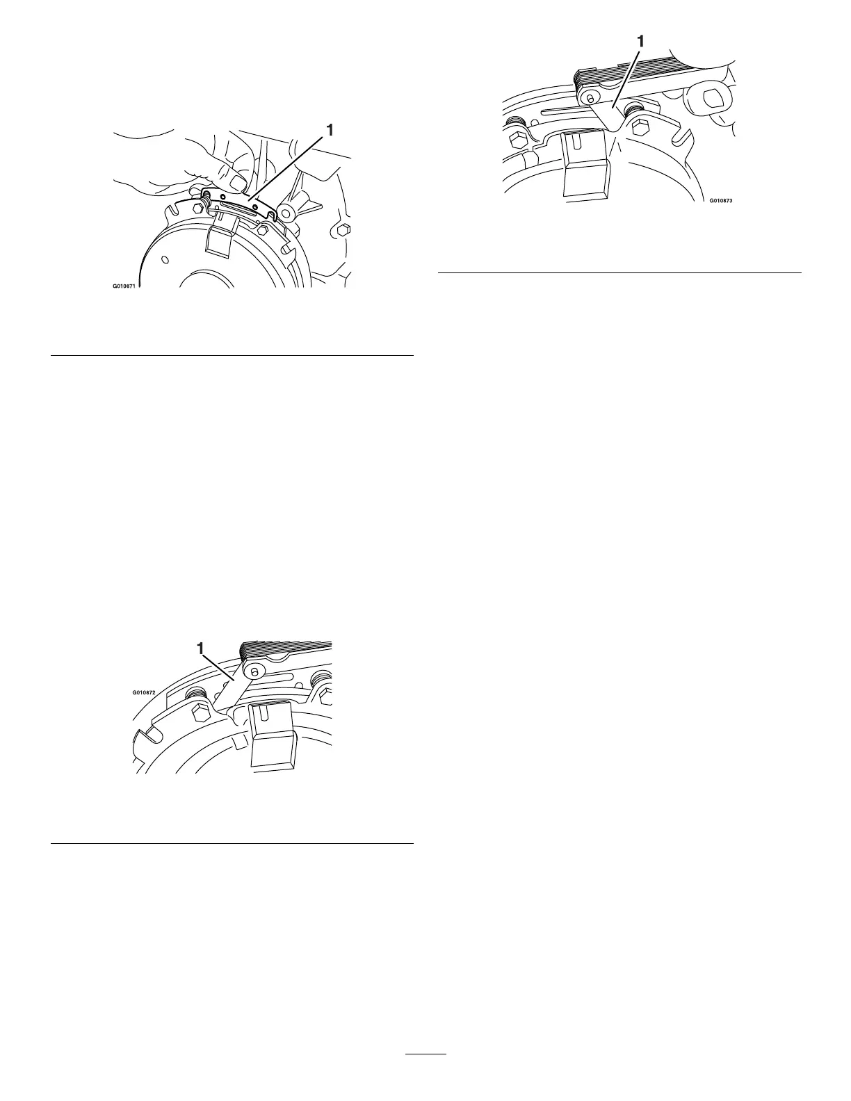
B. Using needle-nose pliers, or by hand, hold
the tab and remove the shim ( Figure 90 ).
Note: Do not discard the shim until the
clutch is functioning properly .
g010871
Figure 90
1. Shim
C. Using a pneumatic line, blow out any debris
from under the brake pole and around the
brake spacers.
D. T orque each bolt (M6 x 1) to 12.3 to 13.7
N∙m (9.5 to 10.5 ft-lb).
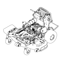
E. Using a 0.25 mm (0.01 inch) thick feeler
gauge, verify that a gap is present between
the rotor and the armature face on both
sides of the brake pole as shown in Figure
91 and Figure 92 .
Note: Due to the way the rotor and the
armature faces wear (peaks and valleys) it
is sometimes dif cult to measure the gap
accurately .
g010872
Figure 91
1. Feeler gauge
g010873
Figure 92
1. Feeler gauge
• If the gap is less than 0.25 mm (0.01
inch), then install the shim.
• If the gap is suf cient, proceed to the
safety check in step F .
F . Perform the following safety check:
i. Sit on the seat and start the engine.
ii. Make sure that the blades do not
engage with the blade-control switch
(PT O) in the O FF position, and that
the clutch is disengaged.
If the clutch does not disengage,
install the shim again.
iii. Engage and disengage the
blade-control switch (PT O) 10
consecutive times to ensure that the
clutch is functioning properly .
64