Reelmaster 5010- HPage 5 - 90Electrical System
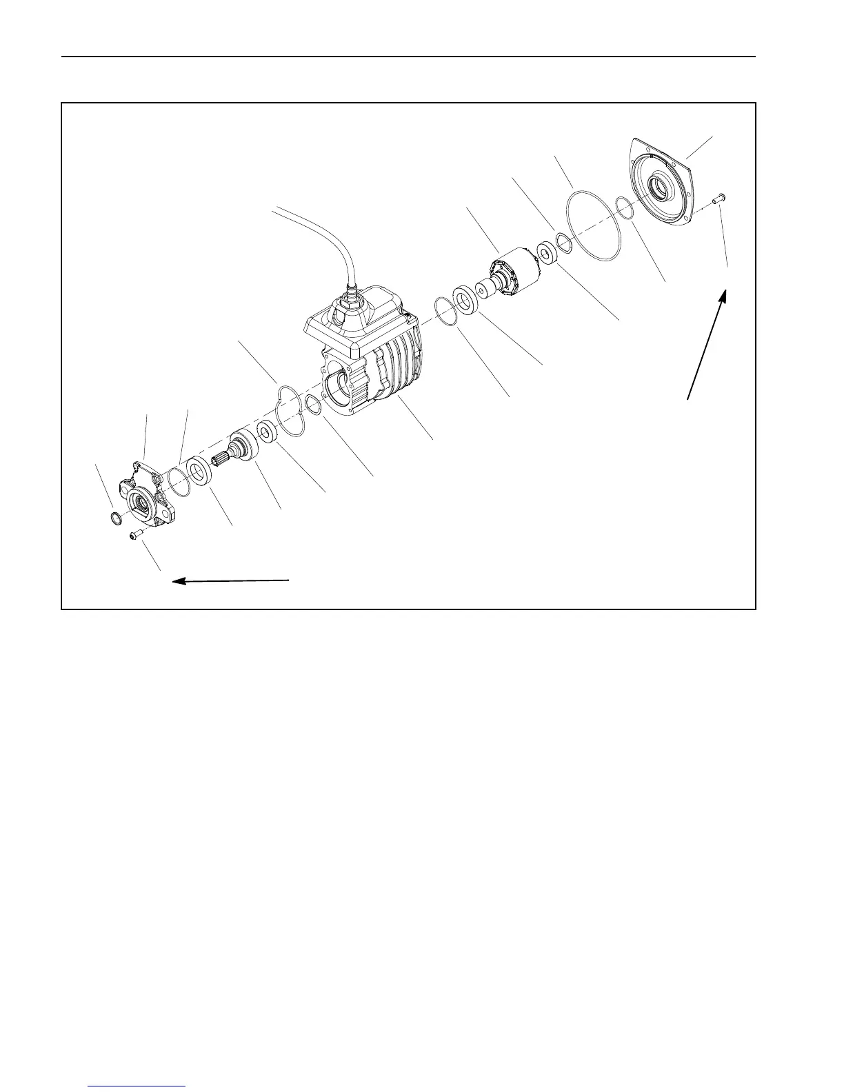
Cutting Reel Motor Service
1. Torx head screw (12 used)
2. Motor cover
3. O- ring
4. Wave washer (2 used)
5. Bearing (2 used)
6. Rotor
7. Bearing (2 used)
8. O- ring (2 used)
9. Housing/controller/cable assembly
10. O- ring
11. Output gear
12. Gearbox cover
13. Shaft seal
14. O- ring
Figure 95
5
7
7
5
6
11
8
1
4
3
10
8
9
12
14
13
2
4
1
70 to 80 in- lb
(8 to 9 N- m)
70 to 80 in- lb
(8 to 9 N- m)
NOTE: If motor housing, controller or cable damage oc-
curs, cutting reel motor replacement is necessary.
These components are not available separately.
IMPORTANT: When working on the cutting reel mo-
tor, use a clean work space with a non- metal sur-
face. The reel motor rotor includes very powerful
magnets that can cause the rotor to move unexpect -
edly if working on a metal s urface. Also, any m etallic
debris that gets attracted to the rotor can damage
the motor after assembly.
Disassembly (Fig. 95)
1. Remove six (6) torx head screws that secure gear-
box cover (item 12) to front of motor housing.
2. Carefully slide gearbox cover from front of motor.
3. Remove and discard O- rings (items 8 and 10) from
gearbox cover.
4. Slide output gear assembly (items 5, 11 and 7) from
motor housing. Remove wave washer (item 4).
5. Remove six (6) torx head screws that secure motor
cover (item 2) to rear of motor housing. Leave cover on
rotor shaft.
IMPORTANT: The rotor magnets are very powerful
and can cause the rotor to shift position very rapidly
during removal. Use cutting reel motor rotor tool set
(see Special Tools in this chapter) to remove rotor.
Be cautious during rotor removal to p revent compo-
nent damage or personal injury.

 Loading...


