Page 4 - 30Hydraulic System
Sand Pro 2040Z
Hydraulic Reservoirs
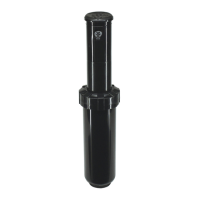
Figure 27
FRONT
RIGHT
1. Hydraulic manifold
2. Transmission (RH shown)
3. Hydraulic reservoir (RH shown)
4. Reservoir bracket (2 used)
5. Flange head screw (2 used per side)
6. Flange nut (2 used per side)
7. Hose clamp (2 used per hose)
8. Flange head screw (2 used per side)
9. Hydraulichose(2used)
10. Fitting (2 used)
11. Flange head screw (2 used)
12. O- ring (2 used)
2
6
8
9
10
11
1
5
7
12
4
3
7
17 to 21 ft- lb
(23 to 28 N- m)
Removal (Fig. 27)
1. Park machine on a level surface, fully lower rear
attachment, stop engine, apply parking brake and re-
move key from ignition switch.
2. Read the General Precautions for Removing and
Installing Hydraulic System Components at the begin-
ning of this section.
3. Place drain pan under transmission for reservoir that
is to be serviced. Make sure that drain pan is large
enough to hold contents of transmission and hydraulic
reservoir (see Specifications in this Chapter).
4. For reservoir that is to be serviced, remove two (2)
transmission drain plugs (pump side and gear drive
side) to allow transmission and hydraulic reservoir to
drain (Fig. 28).
IMPORTANT: Follow all local c odes and regulations
when recycling or disposing hydraulic fluid.
5. Thoroughly clean the end of hydraulic hose (item 9)
at reservoir outlet to prevent hydraulic system contami-
nation.
 Loading...