2.Withthebucketinstalledandangleddownward,
loweritintothegroundsothatthefrontofthe
tractionunitliftsoffthegroundafewcentimeters
(inches).
Note:Ifyoudonothaveabucket,raise
themachineandsupportitusingjackstands
ratedfortheweightofthemachine;referto
Specications(page18).
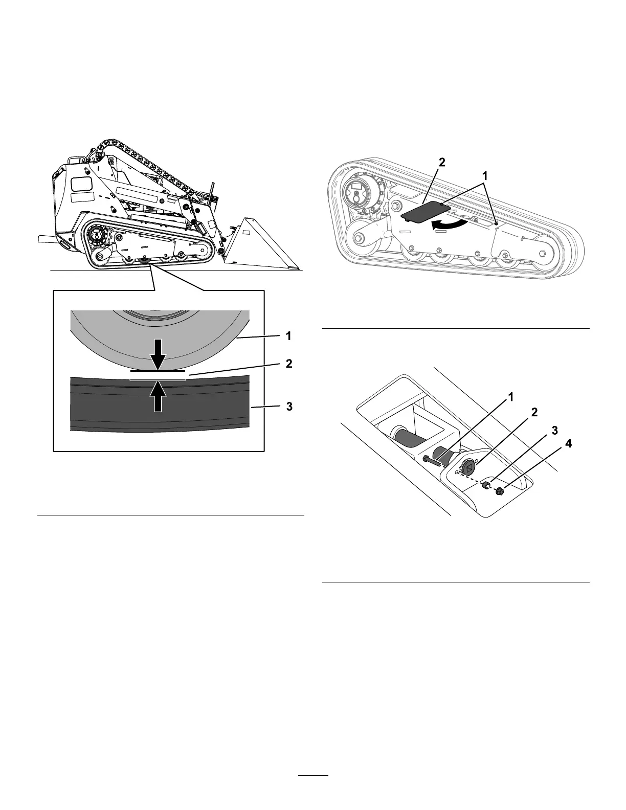
g263492
Figure68
1.Roadwheel3.Track
2.Gapis20mm(0.8inch).
3.Shutofftheengineandremovethekey.
4.Verifythatthegapbetweenthe2ndroadwheel
fromtherearandthetrackis20mm(0.8inch)
asshowninFigure68.Ifadjustmentisneeded,
proceedtoAdjustingtheTrackT ension(page
44)
AdjustingtheTrackTension
1.Parkthemachineonalevelsurfaceandengage
theparkingbrake.
2.Placea15x15cm(6x6inch)blockunderthe
rearframeofthemachine,directlybehindthe
trackbeingtensioned.
3.Withthebucketinstalledandangleddownward,
loweritintothegroundsothatthefrontofthe
tractionunitliftsoffthegroundafewcentimeters
(inches)andthemachinetipsbackontothe
blockuntilthetrackiscompletelyofftheground.
Note:Ifyoudonothaveabucket,raise
themachineandsupportitusingjackstands
ratedfortheweightofthemachine;referto
Specications(page18).
4.Shutofftheengineandremovethekey.
5.Loosenthe2boltsandrotatetheaccesscover
open(Figure69).
g262055
Figure69
1.Bolt2.Accesscover
6.Removethelockingbolt,spacer,andnut(Figure
70).
g262056
Figure70
1.Lockingbolt
3.Spacer
2.Tensioningscrew4.Nut
7.Usinga1/2inchdriveratchet,turnthetensioning
screwuntilthegapbetweentheroadwheeland
trackis20mm(0.79inch)asshowninFigure
68.
Note:Turningthescrewcounter-clockwise
tightensthetrack;turningthescrewclockwise
loosensthetrack.
8.Alignthenotchinthetensionscrewtothe
nearestlocking-boltholeandsecurethescrew
withthelockingbolt,spacer,andnut(Figure70.
9.Repeattheprocedurefortheothertrackif
needed.
44