Chapter
1:
Introduction
TV
front
and
side
panel
controls
and
connections
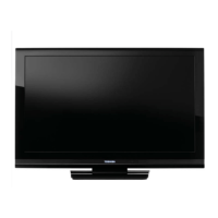
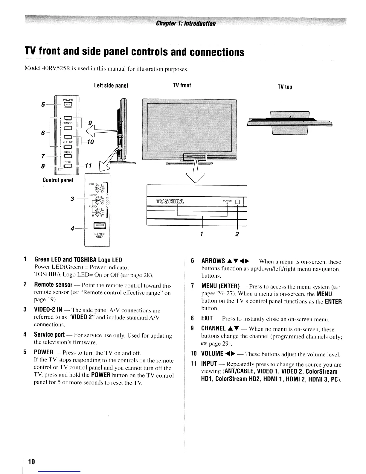
Model 40RV525R
is
used
in
this manual for illustration purposes.
left
side
panel
TV
front
TV
top
Control
panel
If'@@[g]O®L':i
POWER
01
a
I
I
I
I
2
1
VIOE~l
llMONO
~
3-~§
AU~j
4-
u=~
SERVICE
ONLY
~
5-
111
:111
U
h5l
]]-9
I
6 1
0
III
<;-
=
•.
1(;']]-10
~:
IIII
MENU
III
J.
7
1[11~11
8
ijl
EXIT
W
1
Green
LED
and
TOSHIBA
Logo
LED
Power LED(Green) = Power indicator
TOSHIBA Logo
LED=
On
or
Off
(I@f'
page 28).
2
Remote
sensor
- Point the remote control toward this
remote sensor
(I@f'
"Remote
control effective range" on
page 19).
3
VIOEO-2
IN
-
The
side panel
AN
connections are
referred to as
"VIDEO
2" and include standard
AN
connections.
4
Service
port
- For service use only. Used for updating
the television's firmware.
5
POWER
- Press to turn the TV on and off.
If the
TV
stops responding to the controls on the remote
control
or
TV control panel and you cannot turn
off
the
TV, press and hold the
POWER
button on the TV control
panel for
5
or
more seconds to reset the
TV.
6
ARROWS.A.
.......
~
- When a menu
is
on-screen, these
buttons function as up/down/left/right menu navigation
buttons.
7
MENU
(ENTER)
- Press to access the menu system
(~~
pages
26-27).
When a menu
is
on-screen, the
MENU
button on the
TV's
control panel functions as the
ENTER
button.
8
EXIT
- Press to instantly close an on-screen menu.
9
CHANNEL
.A.
... - When no menu
is
on-screen, these
buttons change the channel (programmed channels only;
I@f'
page 29).
10
VOLUME
....
~
-
These
buttons adjust the volume level.
11
INPUT
- Repeatedly press to change the source you are
viewing
(ANT/CABLE,
VIDEO
1,
VIDEO
2,
ColorStream
H01,
ColorStream
H02,
HOMI1,
HOMI
2,
HOMI
3,
PC).
 Loading...