E6581528
G-7
7
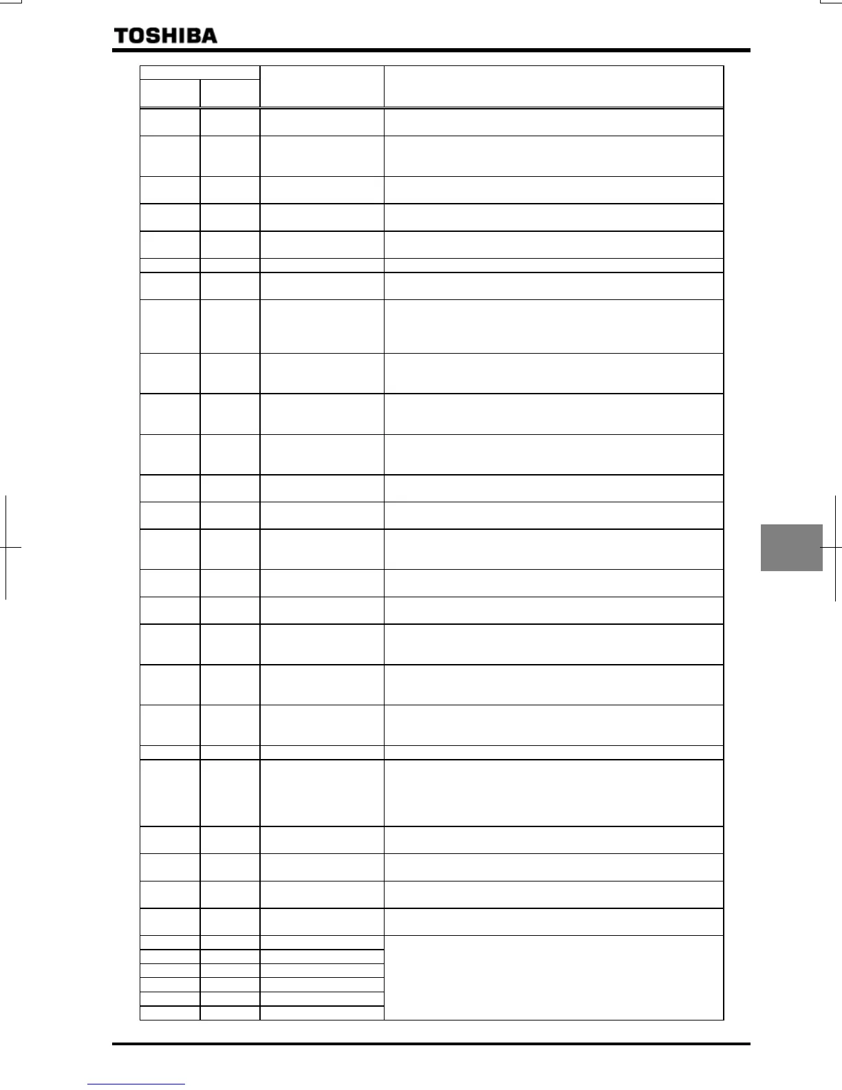
Parameter setting
Positive
logic
Negative
logic
Function Operation output specifications (in case of positive logic)
Over-torque detection
ON:The state that torque component is
, set value
or larger continued more than
set value.
Braking resistor
overload pre-alarm
ON:A certain rate of braking resister overload trip (
)
detection time is over.
OFF:The detection time is within a certain limit.
In emergency stop
ON:In emergency stop operation (
is indicated).
OFF:The detection time is within a certain limit.
In retry
ON:In retry operation (
is indicated).
OFF:No retry operation is performed.
Pattern operation
switching output
ON:In normal operation or pattern operation has finished.
OFF:In pattern operation.
PID deviation limit ON:PID deviation is in or set value.
Run/Stop
ON:Running frequency is output or DC injection breaking (
) is
performed.
Serious failure
(OCA,
OCL, EF, phase failure,
etc.)
ON:Serious failure (
, , , phase failure, abnormal
output, short-circuit) is detected.
OFF:Inverter has recovered from serious failure. (Serious failure
has been reset)
Light failure
(OL, OC1,
2, 3, OP)
ON:Light failure (
, , , , ) is detected.
OFF:Inverter has recovered from light failure. (Light failure has
been reset)
Commercial
power/inverter
switching output 1
Refer to Section 6.19.
Commercial
power/inverter
switching output 2
Refer to Section 6.19.
Cooling fan
ON
/
OFF
ON:Cooling fan is in operation.
OFF:Cooling fan is off operation.
In jogging operation
(In jog run)
ON:In jog run
OFF:In normal operation
Operation
panel/terminal board
operation switching
ON:In operation by terminal board.
OFF:In operation by operation panel.
Cumulative operation
time alarm
ON:Cumulative operation time is beyond the set value.
OFF:Cumulative operation time is less than the
set value.
PROFIBUS/DeviceNet/CC
-Link communication error
ON:Communication error occurred.
OFF:Communication error is canceled (reset).
Forward/reverse
switching
OFF:In forward operation.
ON:In reverse operation.
(The last status is held while operation is suspended.)
Ready for operation 1
ON:In operable status or operation can be started with frequency
command input as an operation switching answer-back.
OFF:In inoperable status.
Ready for operation 2
ON:In operable status or operation can be started with ST and
RUN signals and frequency command input.
OFF:In inoperable status.
Brake release (BR) Output the braking signal according to the brake sequence.
In (pre-)alarm status
ON:More than one of alarm, pre-alarm, undervoltage, low current
over-torque, poor control power supply, PID deviation limit,
abnormal frequency setting or torque limit have occurred or
detected.
OFF:All the alarms above are canceled.
Forward speed limit
(torque control)
ON:Forward operation speed is set value or over.
OFF:Forward operation speed is less than
set value.
Reverse speed limit
(torque control)
ON:Reverse operation speed is set value or over.
OFF:Reverse operation speed is less than
set value.
Inverter healthy
output
ON and OFF are alternately output at intervals of 1 second.
RS485
communication error
ON:Communication error occurred.
OFF:Communication error is canceled (reset).
Error code output 1
Error code output 2
Error code output 3
Error code output 4
Error code output 5
Error code output 6
Output the error code in 6-bit.

 Loading...


