E6581386
E-29
5
[Example: Procedure of calibrating the meter connected to the terminal AM to which “output current” is assigned.]
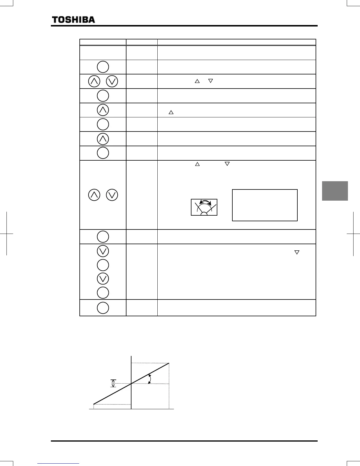
Key operated LED display Operation
–
Displays the operation frequency. (Perform during operation stopped.)
(When standard monitor display selection
= [Output frequency])
The first basic parameter “History function ()” is displayed.
Press either the or key to select “. ”
Pressing the ENTER key allows the reading of parameter setting.
Set the parameter at (fixed output for meter calibration 2) by pressing
the key.
Press the ENTER key to save the change. Then, and the set
value are displayed alternately.
Select the AM terminal meter adjustment by pressing the △ key.
Press the ENTER key to switch to the data display mode.
Press either the key or the key to adjust the meter.
Adjust the pointer to the graduation to which you want it to point when the
inverter passes a current 100% larger than its rated output current.
(The meter reading will change at this time but be careful because there
will be no change in the inverter's indication).
By setup, before the needle of meter beings to sway, it will take time.
Press the ENTER key to save the change. Then and the set value are
displayed alternately.
Select the “AM terminal meter adjustment
” by pressing the
key.
Pressing the ENTER key allows the reading of parameter setting.
Return the parameter setting to (output current display).
Press the ENTER key to save the change. Then, and the set
value are displayed alternately.
Press the MODE key three times to return to the running frequency
display mode. (When standard monitor display selection
=
[Output frequency])
[Procedure of calibrating the output for signed data from 0-10V using FM terminal.]
(Adjustment level: 5V output at 0Hz, 9V output at forward running in FH, 1V output at reverse running in FH)
0
(
Reverse run
)
FM output voltage
(
V
)
9
5
1
(
Forward run
)
FH
FH
MODE
ENT
ENT
ENT
ENT
ENT
ENT
MODE
[Hint]
It's easier to make the
adjustment if you push and
hold for several seconds.
1) Select the switch of SW2 (for FM) to 0-10V side.
2) Set the parameter
= (Signed output
frequency).
3) Set the FM output voltage becomes 5V at 0Hz with
adjusted the parameter
.
4) Set the parameter
= (Signed fixed output 1).
5) Set the FM output voltage becomes 9V with adjusted the
parameter
.
6) Set the parameter
=.
7) Finish
 Loading...