110
RT-SVX24Q-EN
Table 48. Service test guide component operation—evaporative condenser (continued)
Component Being Tested Requirements (ON) Requirements (OFF)
Sump Heater No Requirements No Requirements
Notes:
1. Sump freeze protection is active during AUTO but is inactive in service test modes (head pressure control set to MANUAL).
2. Water treatment drain request will be ignored in service test.
Verifying Proper Fan Rotation
WWAARRNNIINNGG
HHaazzaarrddoouuss SSeerrvviiccee PPrroocceedduurreess!!
FFaaiilluurree ttoo ffoollllooww aallll pprreeccaauuttiioonnss iinn tthhiiss mmaannuuaall aanndd
oonn tthhee ttaaggss,, ssttiicckkeerrss,, aanndd llaabbeellss ccoouulldd rreessuulltt iinn
ddeeaatthh oorr sseerriioouuss iinnjjuurryy..
TTeecchhnniicciiaannss,, iinn oorrddeerr ttoo pprrootteecctt tthheemmsseellvveess ffrroomm
ppootteennttiiaall eelleeccttrriiccaall,, mmeecchhaanniiccaall,, aanndd cchheemmiiccaall
hhaazzaarrddss,, MMUUSSTT ffoollllooww pprreeccaauuttiioonnss iinn tthhiiss mmaannuuaall
aanndd oonn tthhee ttaaggss,, ssttiicckkeerrss,, aanndd llaabbeellss,, aass wweellll aass tthhee
ffoolllloowwiinngg iinnssttrruuccttiioonnss:: UUnnlleessss ssppeecciiffiieedd ootthheerrwwiissee,,
ddiissccoonnnneecctt aallll eelleeccttrriiccaall ppoowweerr iinncclluuddiinngg rreemmoottee
ddiissccoonnnneecctt aanndd ddiisscchhaarrggee aallll eenneerrggyy ssttoorriinngg
ddeevviicceess ssuucchh aass ccaappaacciittoorrss bbeeffoorree sseerrvviicciinngg..
FFoollllooww pprrooppeerr lloocckkoouutt//ttaaggoouutt pprroocceedduurreess ttoo
eennssuurree tthhee ppoowweerr ccaann nnoott bbee iinnaaddvveerrtteennttllyy
eenneerrggiizzeedd.. WWhheenn nneecceessssaarryy ttoo wwoorrkk wwiitthh lliivvee
eelleeccttrriiccaall ccoommppoonneennttss,, hhaavvee aa qquuaalliiffiieedd lliicceennsseedd
eelleeccttrriicciiaann oorr ootthheerr iinnddiivviidduuaall wwhhoo hhaass bbeeeenn
ttrraaiinneedd iinn hhaannddlliinngg lliivvee eelleeccttrriiccaall ccoommppoonneennttss
ppeerrffoorrmm tthheessee ttaasskkss..
NNoottee:: Fans controlled by VFD will run in the correct
direction even if phasing is incorrect.
1. Ensure that the “System” selection switch at the
remote panel is in the Off position and the “Fan”
selection switch for constant volume units is in the
Auto position. (VAV and SZVAV units do not utilize
a “Fan” selection input.)
2. Close the disconnect switch or circuit protector
switch that provides the supply power to the unit
terminal block 1TB1 or the unit mounted disconnect
switch 1S14.
3. Turn the 115 volt control circuit switch 1S2 and the
24 volt control circuit switch 1S3 to the On position.
4. Open the Human Interface access door, located in
the unit control panel, and press the SERVICE
MODE key to display the first service screen. Refer
to the latest edition of the appropriate
programming manual for applications for the
SERVICE TEST screens and programming
instructions.
5. Use to program the unit Fans for operation by
scrolling through the displays. All of the Fans
(Supply, Exhaust, and Condenser) can be
programmed to be “On”, if desired. Refer to Figure
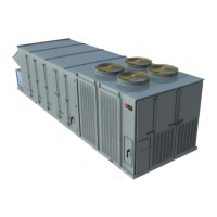
71, p. 111 for the condenser fan locations and the
Human Interface designator.
6. Once the configuration for the Fans is complete,
press the NEXT key until the LCD displays the “Start
test in __Sec.” screen. Press the + key to designate
the delay before the test is to start. TThhiiss sseerrvviiccee
tteesstt wwiillll bbeeggiinn aafftteerr tthhee TTEESSTT SSTTAARRTT kkeeyy iiss
pprreesssseedd and the delay designated in this step has
elapsed. Press the ENTER key to confirm this
choice.
WWAARRNNIINNGG
RRoottaattiinngg CCoommppoonneennttss!!
FFaaiilluurree ttoo ddiissccoonnnneecctt ppoowweerr bbeeffoorree sseerrvviicciinngg ccoouulldd
rreessuulltt iinn rroottaattiinngg ccoommppoonneennttss ccuuttttiinngg aanndd ssllaasshhiinngg
tteecchhnniicciiaann wwhhiicchh ccoouulldd rreessuulltt iinn ddeeaatthh oorr sseerriioouuss
iinnjjuurryy..
DDuurriinngg iinnssttaallllaattiioonn,, tteessttiinngg,, sseerrvviicciinngg aanndd
ttrroouubblleesshhoooottiinngg ooff tthhiiss pprroodduucctt iitt mmaayy bbee
nneecceessssaarryy ttoo wwoorrkk wwiitthh lliivvee aanndd eexxppoosseedd rroottaattiinngg
ccoommppoonneennttss.. HHaavvee aa qquuaalliiffiieedd oorr lliicceennsseedd sseerrvviiccee
iinnddiivviidduuaall wwhhoo hhaass bbeeeenn pprrooppeerrllyy ttrraaiinneedd iinn
hhaannddlliinngg eexxppoosseedd rroottaattiinngg ccoommppoonneennttss,, ppeerrffoorrmm
tthheessee ttaasskkss..
7. Press the TEST START key to start the test.
Remember that the delay designated in step 6 must
elapse before the fans will begin to operate.
8. Check the supply fan and the Exhaust fans (if
equipped) for proper rotation. The direction of
rotation is indicated by an arrow on the fan
housings. Check the condenser fans for clockwise
rotation when viewed from the top.
UUnniitt SSttaarrttuupp

 Loading...


