RT-SVX24Q-EN
59
WWAARRNNIINNGG
PPrrooppeerr FFiieelldd WWiirriinngg aanndd GGrroouunnddiinngg
RReeqquuiirreedd!!
FFaaiilluurree ttoo ffoollllooww ccooddee ccoouulldd rreessuulltt iinn ddeeaatthh oorr
sseerriioouuss iinnjjuurryy..
AAllll ffiieelldd wwiirriinngg MMUUSSTT bbee ppeerrffoorrmmeedd bbyy qquuaalliiffiieedd
ppeerrssoonnnneell.. IImmpprrooppeerrllyy iinnssttaalllleedd aanndd ggrroouunnddeedd
ffiieelldd wwiirriinngg ppoosseess FFIIRREE aanndd EELLEECCTTRROOCCUUTTIIOONN
hhaazzaarrddss.. TToo aavvooiidd tthheessee hhaazzaarrddss,, yyoouu MMUUSSTT ffoollllooww
rreeqquuiirreemmeennttss ffoorr ffiieelldd wwiirriinngg iinnssttaallllaattiioonn aanndd
ggrroouunnddiinngg aass ddeessccrriibbeedd iinn NNEECC aanndd yyoouurr llooccaall//
ssttaattee//nnaattiioonnaall eelleeccttrriiccaall ccooddeess..
Electric Heat Wiring Connection
IImmppoorrttaanntt:: For units with electric heat, complete
tubing connections AFTER completing
wiring connections. See “Tubing
Connections” section.
1. Cut and remove wire ties which hold the electric
control wires together, remove the shield bracket.
Leave the armaflex on the hole with the control
wires.
2. Cut the lowest wire tie which holds the electric heat
power wires to the vertical post on the high side.
3. Route the power wires one by one in to the hole on
the low side end panel and connect them to the
terminal block inside the electric Junction Box or
inside the extended casing section.
NNoottee:: For 8' extended casing units, remove the
panel (this panel weighs approximately 60
pounds) next to the corner post in the low
side to locate the terminal block.
4. Bundle the electric heat power and control wires
with armaflex wrap on the low side end of the unit.
Screw the shield bracket to compress the wire
bundle and create a good seal, see Figure 42, p. 59.
5. Route the electric heat control wires to the Junction
box located on the high side, see Figure 42, p. 59.
Power and Control Wiring Connections
NNoottee:: Complete Power and Control Wiring Connections
after the tubing connections are complete.
1. Discard the clamps and the wire shield which hold
the power and control wires.
2. Make the power and the control wire connections
and route the wires such that they route straight
from the hole at the bottom of the air handler, turn
at right angles and straight up through the bottom
of the high voltage junction box on the condenser
side, see Figure 42, p. 59.
3. Assemble the louvered panels and the corner
panels in the condenser side back in place.
4. Screw the side panels to both the air handler and
condenser side panels to act as filler panels.
5. Finally, assemble the top cover back in place.
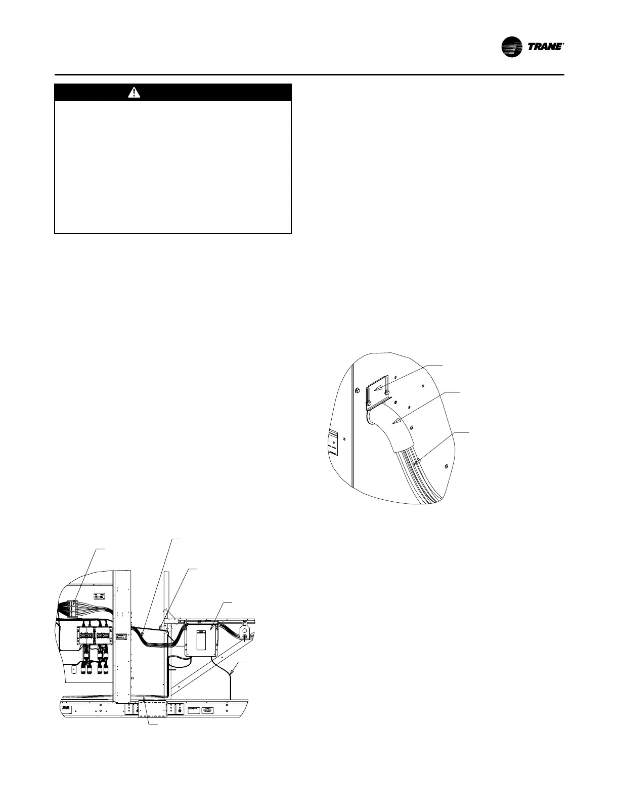
Figure 41. Wire routing at low side end wall
Rain Shield Bracket
Armaflex with
Wire Ties
Electric Heat Power
and Control Wires
Figure 42. Wire routing and connections
Electric Heat Power Wires - Routed through the hole
at the air handler side end wall. Route wires one by one
and connect to the electric heat terminal block.
Electric Heat Control Wires - Routed through
the hole at the air handler side end wall. Remove
wire ties at hole area to improve power wire
routing. Terminate at high voltage junction box.
High Voltage Junction Box
Motor Power Wires are routed through the bottom opening and
terminated at high voltage junction box. Control wires on the right
side of unit have similar routing.
Motor Power Wires and Heater
Control Wires from the main
control box will be terminated at
the high voltage junction box by
the factory.
Electric Heat
Terminal Block
IInnssttaallllaattiioonn

 Loading...


