68
RT-SVX24Q-EN
Table 26. Gas heat inlet sizes (continued)
Standard Gas Heat Input
(MBh) Gas Heat Inlet Sizes (in.)
1800
1 1/2
2500
1 1/2
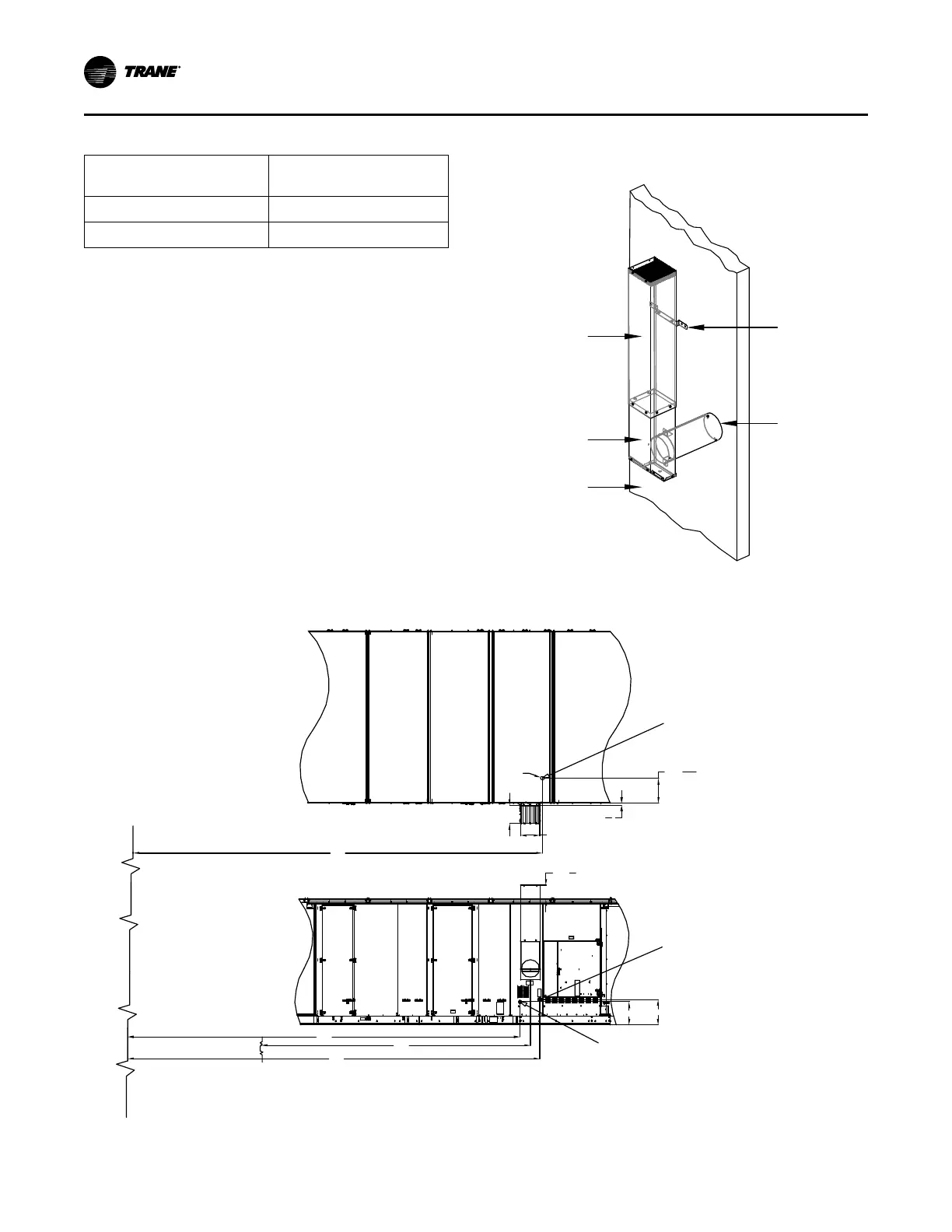
Flue Assembly Installation
1. Locate the collapsed flue assembly in the
compartment above the gas heat controls by
removing the panel screws. The assembly is
secured by screws up through the roof of the gas
controls compartment roof.
2. Separate the pieces of the collapsed assembly and
then assemble the stack as shown in Figure 51, p.
68.
3. Insert the tube on the flue assembly into the hole
located in the vertical support for the heat section.
4. Butt both tube sections together and center the pipe
clamp over joint.
5. Using the pre-punch hole in the flue assembly,
extension, and the vertical support, install the
appropriate number of mounting brackets (Refer to
the installation instructions that ship with the flue
assembly.)
Figure 51. Flue assembly
Flue
Extension
Mounting
Bracket
Flue Tube
Vent Cap
Assembly
Heat Section
Vertical Support
Figure 52. Gas heat piping penetration locations
K
1
7
8
11
5
8
W
D
2.5M & 1.8M (W=16 1/8in, D=14 11/16in)
1.1M, 0.8M (W=9 15/16in, D=9 12/16in)
H
C
21
19
20
7
16
B
Horizontal gas pipe inlet
Pipe type: Black pipe, sch 40
Condensate drain outlet
Pipe type: cpvc
Hole at the base
Ø3
Unit end plane
Edge of mist eliminator
Top View
Side View
IInnssttaallllaattiioonn

 Loading...


