90
RT-SVX24Q-EN
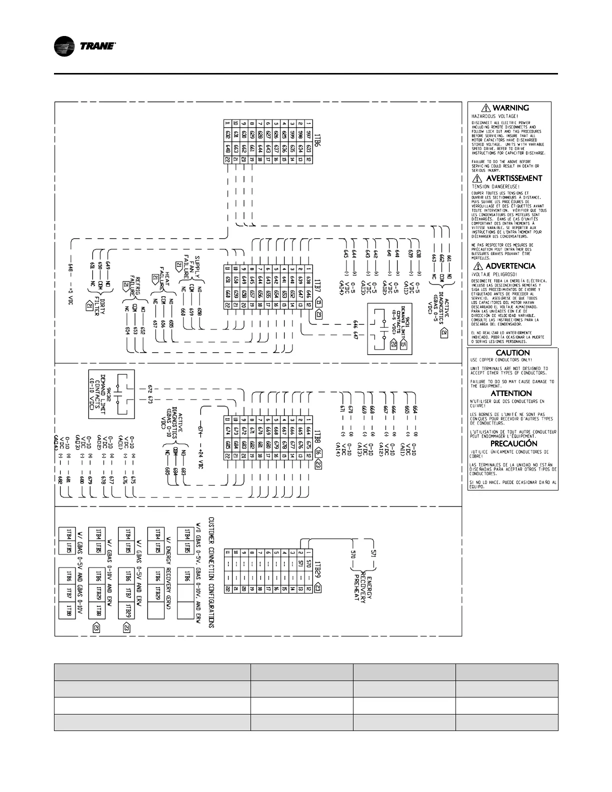
Figure 63. Typical GBAS analog input wiring diagram for 90 to 162 ton CV and VAV control options
Table 44. GBAS voltage vs. setpoint
Setpoint
GBAS 0-5 VDC GBAS 0-10 VDC
Valid Range
Occ Zone Cooling Setpoint (CV only)
0.5 to 4.5 VDC 0.5 to 9.5 VDC 50 to 90°F
Unocc Zone Cooling Setpoint
0.5 to 4.5 VDC 0.5 to 9.5 VDC 50 to 90°F
Occ Zone Heating Setpoint (CV only)
0.5 to 4.5 VDC 0.5 to 9.5 VDC 50 to 90°F
IInnssttaallllaattiioonn

 Loading...


