INSTRUCTION MANUAL
UG30 CONTROL
12 (44)
mP30-UG30 - Rev. 1.5 - Date: 18-03-2004 EN
Dip switch 1-not used
Dip switch 2 set to ON: Relay not energized (contact open) with at least one alarm active, otherwise energized
(contact closed)
Dip switch 3 set to ON
Dip switch 4 set to OFF
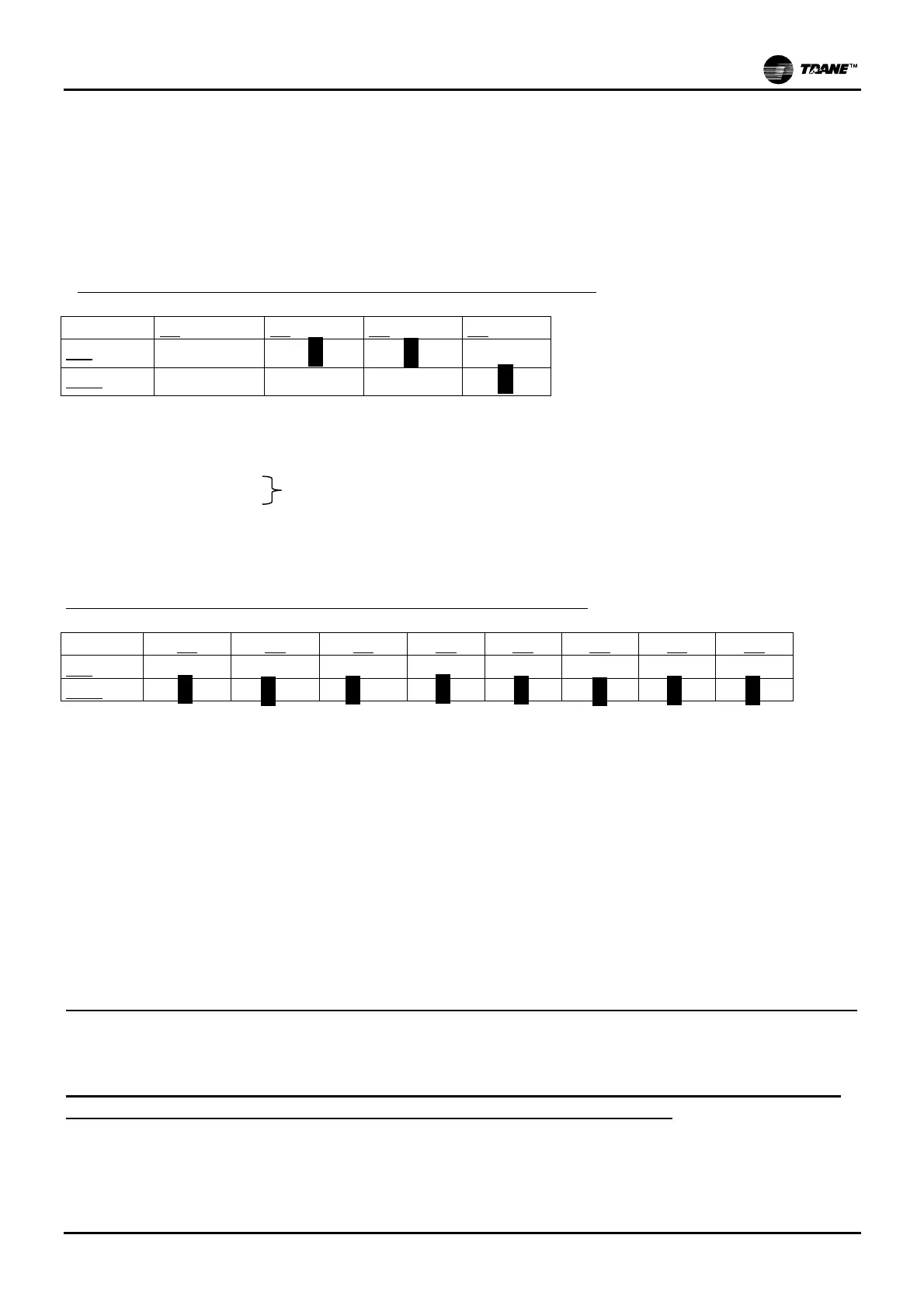
. Dip switches type A (alarm relay and maximum production settings)
A1
A2 A3 A4
ON
X
OFF
X
Dip switch 1-not used
Dip switch 2 set to ON: Relay not energized (contact open) with at least one alarm active, otherwise energized
(contact closed)
Dip switch 3 set to OFF
Dip switch 4 set to ON
Dip switches type B (auxiliary functions and automatic draining time)
B1 B2 B3 B4 B5 B6 B7 B8
ON
OFF
Dip switch 1 set to OFF: complete draining after 7 days without production being requested (function
enabled)
Dip switch 2 set to OFF: automatic draining with or without electrode power supply (electrodes not
supplied)
Dip switch 3 set to OFF: the new production setpoint is reached by means of evaporation cycles when
demand is reduced by less than 25%. Draining is achieved by means of evaporation cycles.
Dip switch 4 set to OFF: cylinder exhaustion advance warnings (alarms are displayed when the cylinder
is approaching exhaustion).
Dip switches 5-6 set to OFF: automatic draining time (default setting)
Dip switches 7-8 set to OFF: Evaporation time threshold (default setting)
The “TA RATE” dip switches are left in their default positions since an external TAM is being used
Jumper setting on external TAM
IN MERCURY/MERCURY BIG MODELS, THE JUMPER MUST BE PLACED IN POSITION
100 (END OF SCALE IS QUANTIFIED IN AMPERES 100=10 AMPERES)
50% of nominal steam flow FRAME 1-2
75% of nominal steam flow FRAME 3-4 & BIG