RTHD-SVX01D-EN 141
Maintenance Procedures
6. Place the cartridge in the nut after filling the bowl with the proper amount
of refrigerant oil (see Step 5). Turn the new nut assembly counterclock-
wise and tighten securely.
7. Connect manifold gauge set at oil charging valve and evacuate the filter to
500 microns.
8. Charge the oil line back with the amount of oil removed. Open the isola-
tion valves to the oil supply system.
Replacing the Gas Pump Oil Filter
The filter element in the gas pump circuit may need to be changed if the gas
pump is unable to return the oil to the compressor.
An evaporator logged with oil will have a high liquid level when referring to
the liquid level sensor, low suction pressures, and higher than normal
approach on the evaporator.
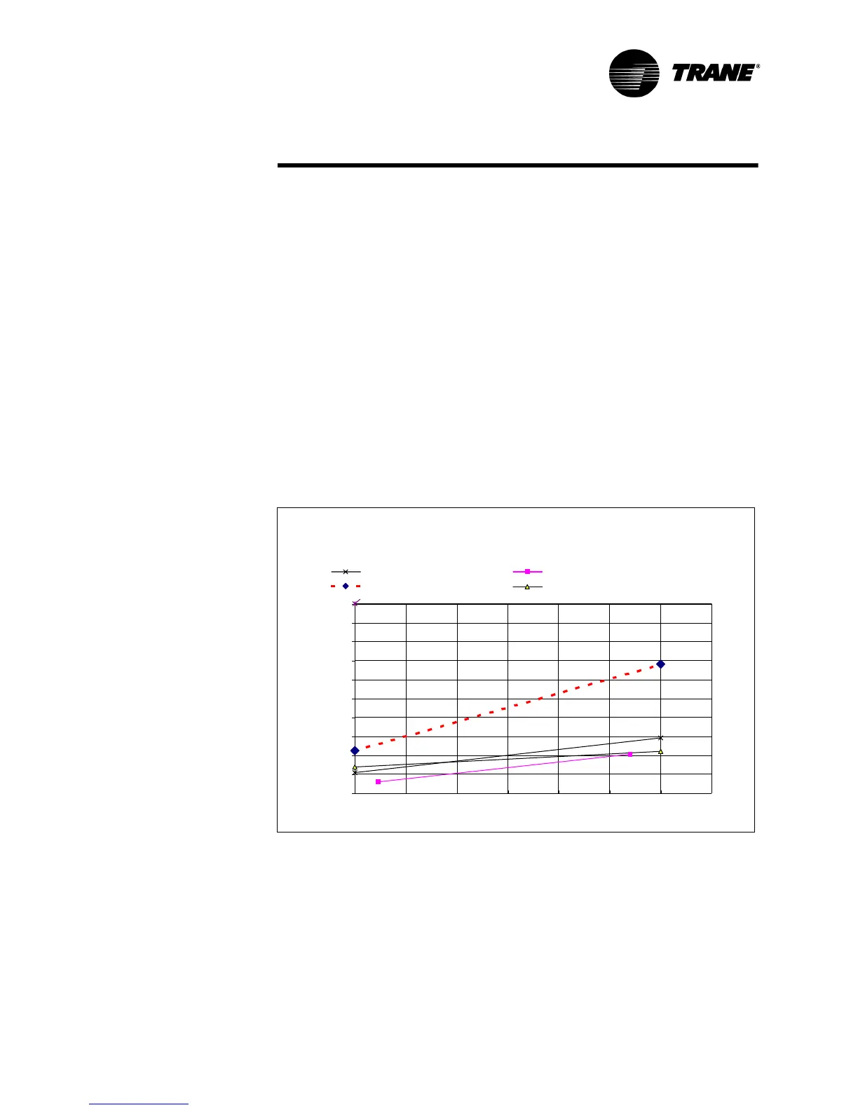
Refer to Figure 45 to determine if the pressure drop across the filter is above
the normal range at full load conditions. Once the oil is logged in the evapora-
tor, it may be necessary to manually move the oil from the evaporator to the
oil sump to avoid losses in the main oil lines.
Refrigerant Charge
If a low refrigerant charge is suspected, first determine the cause of lost
refrigerant. Once the problem is repaired follow the procedures below for
evacuating and charging the unit.
Evacuation and Dehydration
1. Disconnect ALL power before/during evacuation.
Figure 45 Oil Filter Replacement Chart (E,D, C and B Frame Compressors)
Oil Filter Replacement Chart
0
5
10
15
20
25
30
35
40
45
50
20 40 60 80 100 120 140 160
Condensing Press - Suction Press (psid)
Oil Filter Press Drop (psid)
D- and E-Frame Normal Press Drop C-Frame Normal Press Drop
Max Pressure Drop B-Frame Normal Press Drop