RTHD-SVX01D-EN 29
Installation Mechanical
Alternate Moving Method
6. If it is not possible to rig from above as shown in the figures, the unit may
also be moved by jacking each end high enough to move an equipment
dolly under each tube sheet support. Once securely mounted on the dol-
lies, the unit may be rolled into position.
Isolation Pads
The elastomeric pads shipped (as standard) are adequate for most instal-
lations. For additional details on isolation practices, refer to
Trane Engineering Bulletin -Series R
Chiller Sound Ratings and Installa-
tion Guide., or consult an acoustical engineer for sound-sensitive installa-
tions.
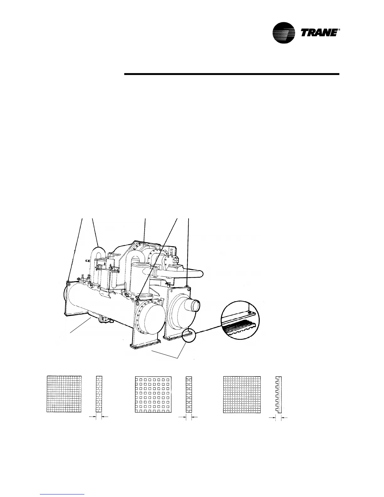
7. During final positioning of the unit, place the isolation pads under the
evaporator and condenser tube sheet supports as shown in Figure 7.
Level the unit as described in the next main paragraph.
NOTE: Durometer values for isolator pads are a measure of resilience. See
Figure 7.
Figure 7 Isolator Pad Placement
Note: Level unit to 1/4” (6.35 mm) across
Typical Elastomeric
Pads extend the full
width of legs
Isolation Pad
Durometer: 50 +/-5
width and length
0.31
0.31
0.31
Durometer: 40 +/-5 Durometer: 55 +/-10
A (hidden leg)
B
C
D