30 RTHD-SVX01D-EN
Installation Mechanical
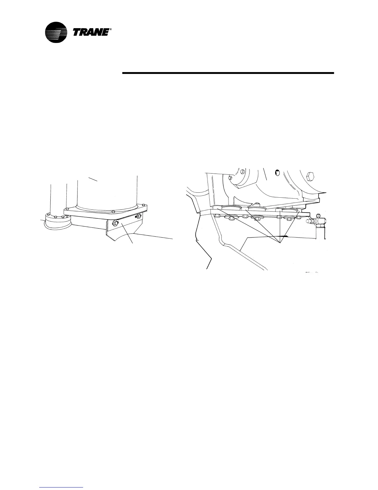
8. The unit is shipped with four spacers (only three on B family) on the com-
pressor mount that protect the compressor isolation pads during shipping
and in handling. Remove these spacers (Figure 8) before the unit is oper-
ated.
9. Remove the shipping brackets from the bottom sides of the oil separa-
tor(s) (see Figure 8).
NOTE: Once shipping bracket(s) is removed, the oil separator is only
supported by the discharge line.
Unit Leveling
NOTE: The electrical panel side of the unit is designated as the “front” of
the unit.
1. Check unit level end-to-end by placing a level on the top surface of the
evaporator shell.
2. If there is insufficient surface available on the top of the evaporator shell,
attach a magnetic level to the bottom of the shell to level the unit. The
unit should be level to within 1/4” (6.35 mm) over its length.
3. Place the level on the evaporator shell tube sheet support to check side-
to-side (front-to-back) level. Adjust to within 1/4” (6.35 mm) of level front-
to-back.
NOTE: The evaporator MUST be level for optimum heat transfer and unit
performance.
4. Use full-length shims to level the unit.
Figure 8 Oil Separator with Shipping Bracket and Compressor Shipping Spacer
Shipping Bracket
Oil Separator
Remove 4 Shipping
Spacers (only 3 on B
Compressor
Housing
M20 bolt
family)