28 RTHD-SVX01D-EN
Installation Mechanical
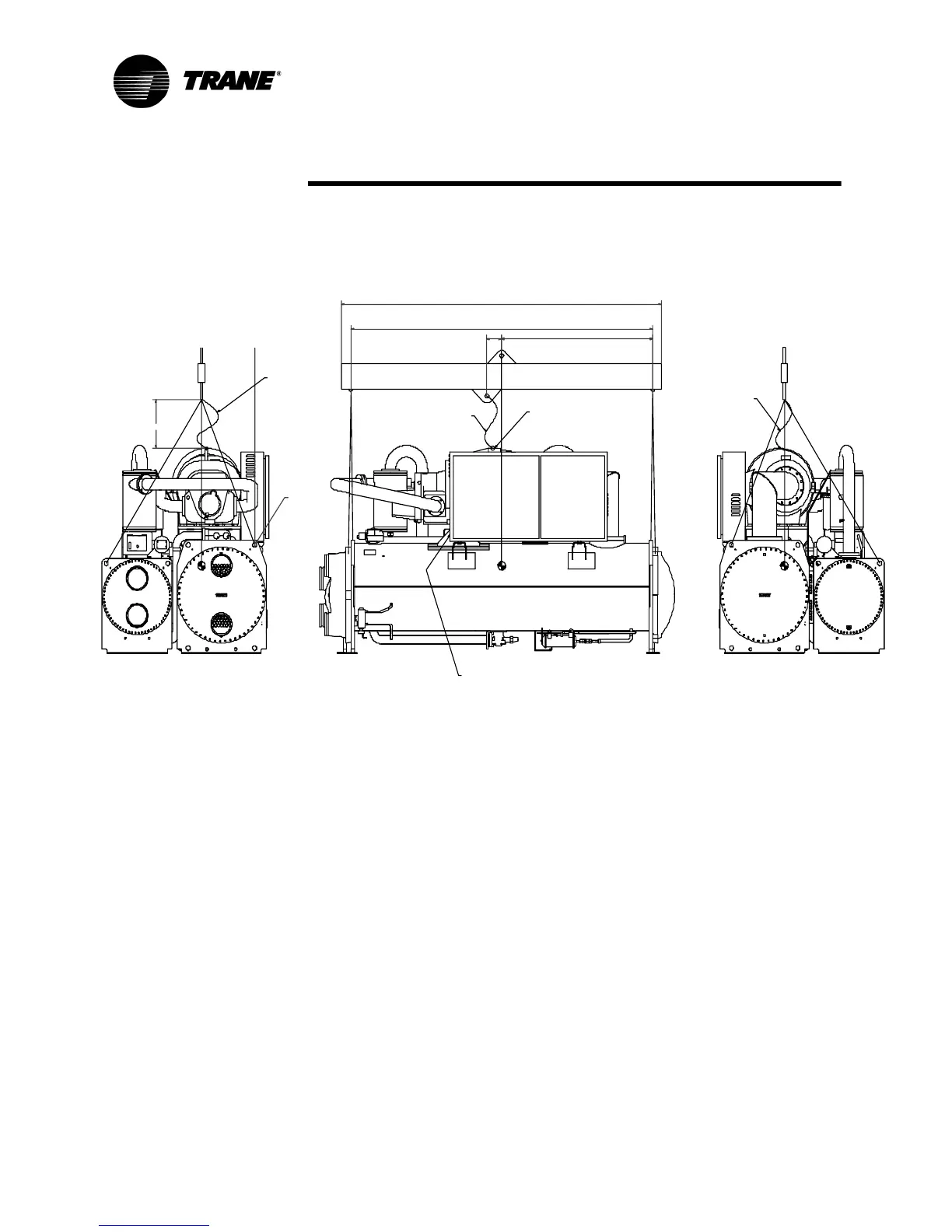
4. Attach cables to lifting beam. Total lifting weight, lifting weight distribution
and required lifting beam dimensions are shown in the rigging diagram
shipped with each unit and in Figure 6. The lifting beam crossbar must be
positioned so the lifting cables do not contact unit piping or electrical
panel enclosure.
WARNING
Anti- rotation Strap!
Connect an anti-rotation strap between the lifting beam and
compressor before lifting unit. Failure to do so may result in death
or serious injury should a lifting cable fail.
5. Connect an anti-rotation strap or cable loosely between the lifting beam
and the threaded coupling or eyelet provided at the top of the compres-
sor. Use an eyebolt or clevis to secure the strap at the coupling or eyelet.
NOTE: The anti-rotation strap is not a lifting chain, but a safety device to
ensure that the unit cannot tilt during lifting.
Figure 6 Lifting the Unit
E
F(MIN)
ANTI-ROLLING
CABLE
ANTI-ROLLING CABLE
ANTI-ROL LING CABLE
B
A
C
UN IT MO DE L NUMBE R LOCATIO N
CON D EVAP
EVAP
COND
STARTER C ONTROLS
EYELET OR M16 INTERNAL T HREAD
D
LIFTING HOLES
n
44 ,5 MM TYP
NOTES:
1. LIFTING CABLES (CHAIN S) WILL NOT BE TH E SAME LEN GTH.
ADJUST TO KEEP UNIT LEVEL WHILE LIFTING.
2. ATTACH ANTI-RO LLING C ABL E (CH AI N) AS SHO WN WITHOUT TENSION.
NOT AS A LIFTING CABLE, BUT TO PREVENT U NIT FROM ROL LIN G.
3. DO NO T F ORK LIFT UNIT.
4. WEIGHTS ARE T YPICAL FOR U NITS W ITH R-13 4a CHARG E.
5. IF U NIT IS DISASSEMBLED, SEE SERVICEBU LLETIN
FORLIFTING ANDRIGGINGOFCOMPONENTS.
WARNING: D O NOT USE CABL ES (CHAINS) OR SLINGS EXCEPT AS SHOWN.
OTHER LIFTING ARRANGEMENTS MAY C AU SE EQU IPMENT DAMAGE OR
SERIOUS PERSONAL INJURY.