General Information and Checkout Procedure Measurement Expected Value
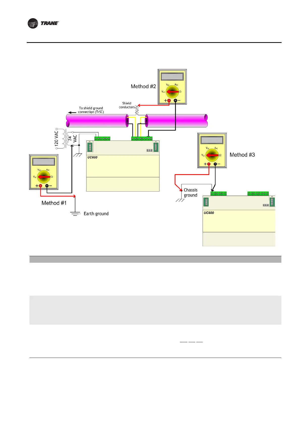
Method 1:
AC voltage between shield conductors and device chassis ground- the
voltage difference between BACnet MS/TP device chassis ground connections
should be close to zero. If the voltage difference is greater that 4.0 Vac, there
will be marginal communication or intermittent communication problems. If the
voltage difference is greater that 7.0 Vac, some devices will no longer
communicate.
Measure AC current across
the current termination and
confirm that only one end of
the shield conductor is tied
to the earth ground
Vac ≤ 2.0 V
Method 2:
AC voltage between earth ground and device chassis ground- the
chassis ground of the UC600 needs to be connected to earth ground by some
route.
Note: Do not assume that the building frame is a valid earth ground.
Measure AC current across
the current termination and
confirm that only one end of
the shield conductor is tied
to the earth ground
Vac ≤ 4.0 V
(Must comply with National
Electrical Code™ and local
electrical codes)
Method 3:
AC voltage between case (nominal chassis ground) and device chassis
ground connector- in this illustration the connection appears as a short.
However, it is possible that the chassis ground connection on the controller may
actually be connected to the equipment metal some distance away. Use this
measurement method if there are communication issues or input stability
problems.
Measure AC voltage across
the current termination. For
this measurement, confirm
that only
one end of the
shield conductor is tied to
the earth ground.
Vac ≤ 4.0 V
(Must comply with National
Electrical Code™ and local
electrical codes)
Typically, this should be
Vac ≤ 1.0 V