24 BAS-SVX45F-GB
Wiring and Powering the Tracer UC600
Transformer Requirements
• AC transformer requirements: UL listed, Class 2 power transformer, 24 VAC ±15%, device max
load 26 VA. The transformer must be sized to provide adequate power to the UC600 controller
(26 VA) and any external device outputs.
• DC power can be used for 4-20 mA devices and up to two expansion modules (XM30, XM32)
and one WCI.
• Include in the total power budget any devices that are powered from the 24 VAC terminal.
• CE-compliant installations: The transformer must be CE marked and SELV compliant per IEC
standards.
Avoid Equipment Damage!
Sharing 24 VAC power between controllers could cause equipment damage.
A separate transformer is recommended for each controller. The line input to the transformer must
be equipped with a circuit breaker sized to manage the maximum transformer line current.
If a single transformer is shared by multiple UC600 controllers:
• The transformer must have sufficient capacity.
• Polarity must be maintained for every UC600 controller powered by the transformer.
Important: If polarity is inadvertently reversed between controllers that are powered by the same
transformer, a difference of 24 VAC will occur between the grounds of each controller.
The following symptoms could result:
–Partial or full loss of communication on the entire BACnet MS/TP link.
–Improper function of UC600 controller outputs.
–Damage to the transformer or a blown transformer fuse.
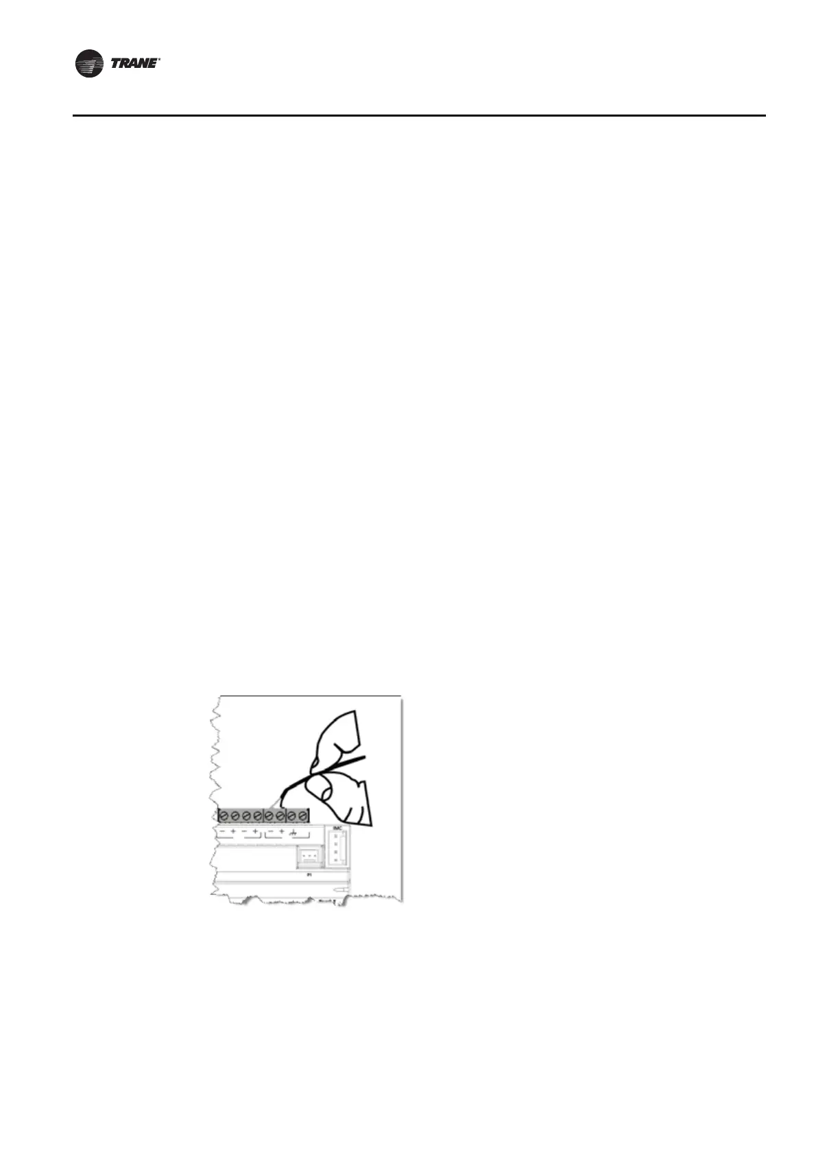
Terminal Connectors and Tug Test
When wiring to the UC600 using terminal connectors, strip the wires to expose 7 mm of bare wire.
Insert each wire into a terminal connector and tighten the terminal screw. A tug test is
recommended after tightening terminal screws to ensure all wires are secure.

 Loading...


