BAS-SVX45F-GB 31
Wiring Inputs and Outputs
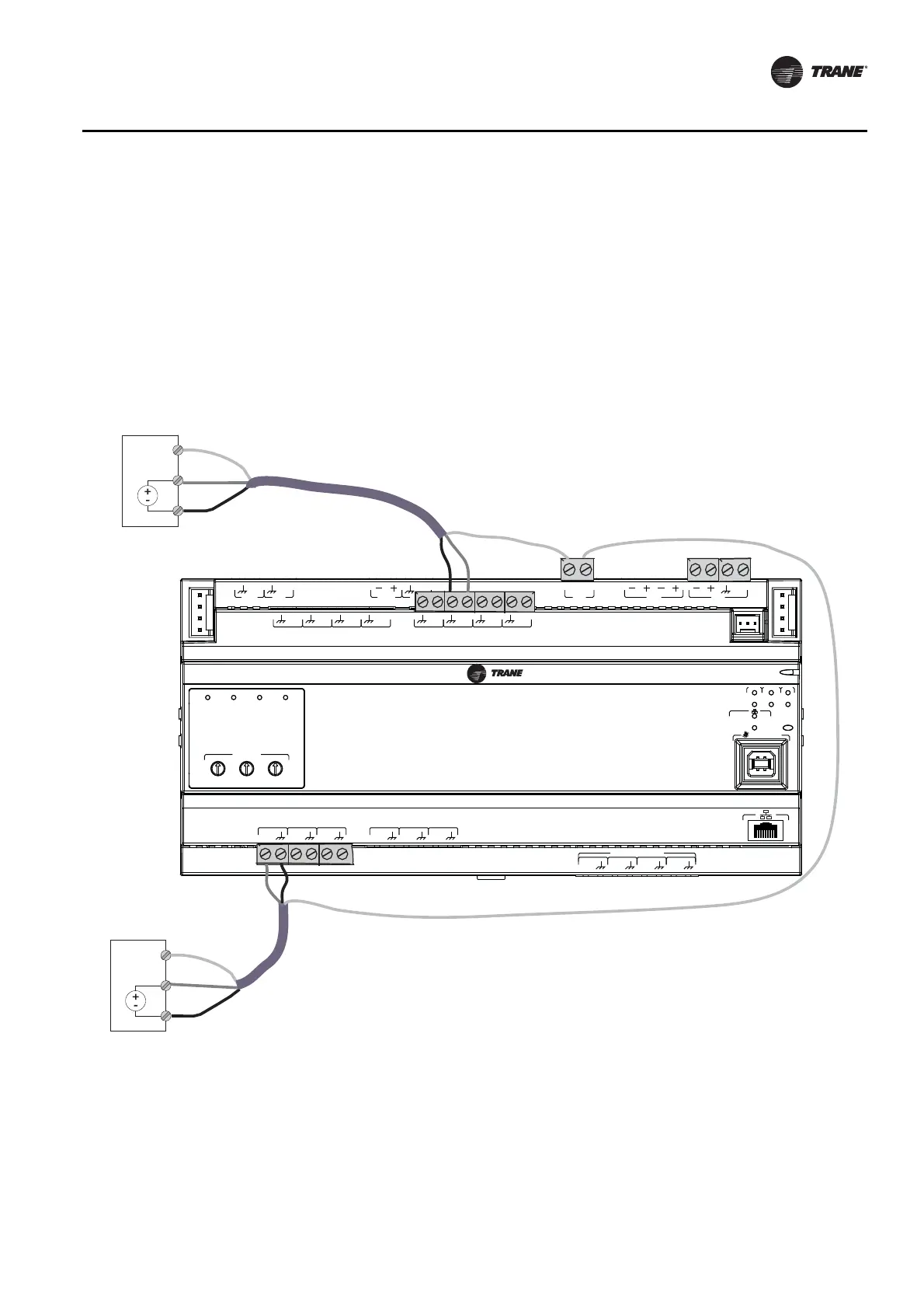
Wiring 0–10 VDC Analog Inputs
Connect 0–10 VDC analog inputs to sensors such as indoor air quality sensors and pressure
sensors. Wiring can be done on the top tier or the bottom tier by using a combination of universal
and analog input terminations.
To wire a 0–10 VDC analog input:
1. Connect the shield wire (as common connection) to a common terminal as shown in Figure 11 .
2. Connect the signal wire to an available input terminal.
3. Connect the supply wire to a 24 VDC or 24 VAC terminal as required.
4. Use the Tracer TU service tool to configure the analog input that references the corresponding
hardware termination.
Figure 11. Typical wiring, 0–10 VDC
IM
C
IM
C
A
O
6
UI
14
A
O
5
UI
13
A
O
4
UI
12
A
O
3
UI
11
A
O
2
UI
10
A
O
1
UI
9
B
O
4
B
O
3
B
O
2
B
O
1
RELAYS
0
.
5
A MAX
1
P
1
UI
8
UI
7
UI
6
UI
5
UI
4
UI
3
UI
2
UI
1
IMC
+
24
VDC
LINKOUT
+
24
VDC
+
24
VDC
OUT
24
VAC
MBUS
OUT
24
VAC
XFMR
24
VAC
SERVICE TOOL
SERVI
C
E
LINK
ACT
IM
C
MBUSLINK
RX
TX
U
C
600
ADDRESS
0
1
2
3
4
5
6
7
8
9
x1
0
1
2
3
4
5
6
7
8
9
x10
0
1
2
3
4
5
6
7
8
9
x100
B
O
4
B
O
3
B
O
2
B
O
1
24 VDC
0-10 VDC ou
t
Common
24 VDC
0-10 VDC out
Common
Top tier wiring: Connect to any
universal input (UI1 through UI8).
Bottom tier wiring: Connect to any
AO/UI input. Connect 24 VDC wire to
available 24 VDC on top tier.

 Loading...


