BAS-SVX45F-GB 35
Wiring Inputs and Outputs
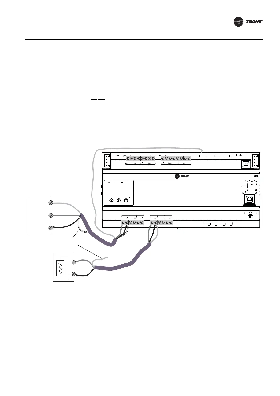
Wiring Analog Outputs
The UC600 has six analog output terminations. These outputs can be used for 0–10 VDC outputs
or 0–20 mA outputs and used to control actuators or secondary controllers. To wire an analog
output:
1. Connect the shield to a common terminal at the terminal board and tape it back at the input
device.
Note: Do Not use the shield as the common connection. For 2-wire applications, use a 2-
conductor cable with separate shield.
2. Connect the signal wire to an available output terminal.
3. Connect the supply wire to a 24 VDC or 24 VAC terminal as required.
4. Use the Tracer TU service tool to configure the analog output that references the corresponding
hardware termination.
Figure 15. Typical wiring, analog outputs
A
O
6
UI
14
A
O
5
UI
13
A
O
4
UI
12
A
O
3
UI
11
A
O
2
UI
10
A
O
1
UI
9
B
O
4
B
O
3
B
O
2
B
O
1
RELAYS
0
.
5
A MAX
IM
C
1
IM
C
P
1
UI
8
UI
7
UI
6
UI
5
UI
4
UI
3
UI
2
UI
1
IMC
+
24
VDC
LINK
OUT
+
24
VDC
+
24
VDC
OUT
24
VAC
MBUS
OUT
24
VAC
XFMR
24
VAC
SERVICE TOOL
SERVI
C
E
LINK
ACT
IM
C
MBUSLINK
RX
TX
U
C
600
ADDRESS
0
1
2
3
4
5
6
7
8
9
x1
0
1
2
3
4
5
6
7
8
9
x10
0
1
2
3
4
5
6
7
8
9
x100
B
O
4
B
O
3
B
O
2
B
O
1
Common
Common
Signal
Signal
24 VDC
Tape back shield
0-20 mA
0-10 volt