Installation - Zone Sensors
64 UNT-SVX07E-EN
4. Follow the instructions given in “Interconnection
Wiring,” page 79 and route the wires as shown in the
wiring diagram. Refer to the typical wiring diagram or
to the unit specific diagram on the unit.
5. Position the fan mode switch over the junction box
with the two screws supplied.
Wired Zone Sensor
Refer to the unit wiring schematic for specific wiring
details and point connections.
1. Note the position of the setpoint adjustment knob and
gently pry the adjustment knob from the cover using
the blade of a small screwdriver.
2. Insert the screwdriver blade behind the cover at the top
of the module and carefully pry the cover away from
the base.
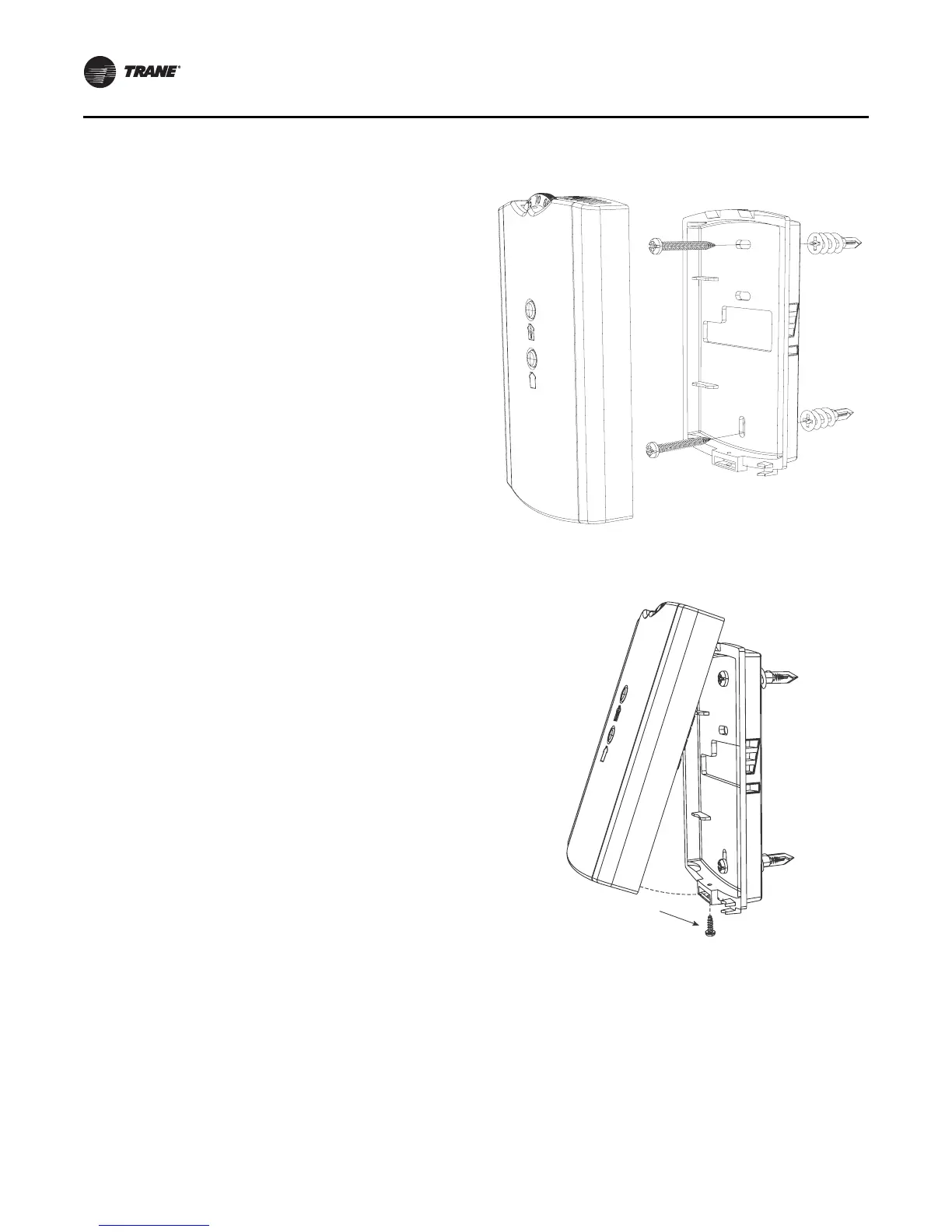
3. To mount the sensor back plate: (see Figure 49).
a. Hold the back plate against the mounting surface
and mark the screw locations.
b. Secure the back plate against the mounting surface
using included hardware.
4. To install the zone sensor module to a standard
junction box:
a. Level and install a 2 x 4-in. junction box (installer
supplied) vertically on the wall.
b. Pull the control wires through the cutout. Attach the
module to the wall using the screws provided.
5. Strip the insulation on the interconnection wires back
0.25-inch and connect to TB1 (for wired sensors).
6. Screw down the terminal blocks (for wired sensors).
7. To replace the cover:
a. Hook the cover over the top of the back plate. Apply
light pressure to the bottom of the cover until it
snaps in place.
b. Install the security screw into the bottom of the
cover if desired (see Figure ).
Wireless Zone Sensors
1. Note the position of the setpoint adjustment knob and
gently pry the adjustment knob from the cover using
the blade of a small screwdriver.
2. Insert the screwdriver blade behind the cover at the top
of the module and carefully pry the cover away from
the base.
3. To mount the sensor back plate: (see Figure 49)
Figure 49. Mounting sensor base plate
Figure 50. Security screw on bottom of sensor

 Loading...

