ECM Overview and Setup
UNT-SVX07E-EN 89
User Interface
The VelociTach motor control board’s on-board user
interface is easy to use and supports:
• Verification/auditing of on-board parameter settings
(read-only)
• Adjustment of the on-board settings (write)
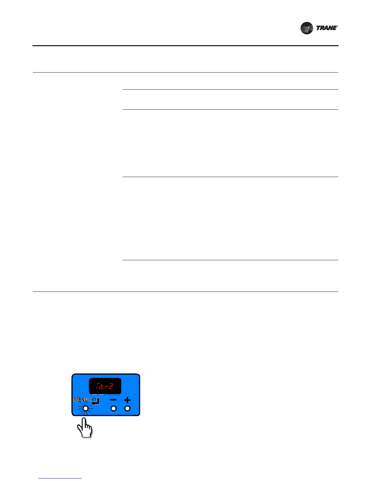
The user interface has three input buttons (see Figure 79),
from left to right:
•“Menu/Set”
• “Decrement”
• “Increment”
Each button has several different actuation levels
depending on length of press, and what the UI is currently
displaying.
Figure 78. Operational Status Codes
RPM Mode
RUNNING/ FAN STATUS
CONTINUOUS LOOP
Displayed when:
1) No error codes are present
2) Motor has completed ramping
Indicates the current rpm of Motor 1 in the system. “0” rpm
here indicate that no fan speed has been requested.
→
Indicates the current rpm of Motor 2 in the system. “0” rpm
here indicate a fan off condition OR a fan “missing”
condition
(a)
.
→
Indicates the status being calculated or Fan Motor 1. If “off,”
this indicates that either:
1) No fan speed is being requested or
2) The fan performance is failing to meet the request; refer
to “ECM Motors,” page 148 for additional troubleshooting
information.
If “on,” this indicates that the fan is performing correctly and
will be used to report fan status correctly, depending on
mode.
/
Indicates the status being calculated or Fan Motor 2. If “off,”
this indicates that either:
1) No fan speed is being requested or
2) The fan performance is failing to meet the request; refer
to “ECM Motors,” page 148 for additional troubleshooting
information.
3) If the target speed for Motor 2 is “0,”this is used to
indicate a missing motor
(a)
.
If “on,” this indicates that the fan is performing correctly and
will be used to report fan status correctly, depending on
mode.
/
Indicates that the temperature sensing circuit has calculated
a logical “on” based on the settings of the following
parameters:
/
/
/
(a) Motor 1 is the only motor in fan coil units.
Figure 79. User interface input buttons

 Loading...

