Installation - Zone Sensors
UNT-SVX07E-EN 65
a. Hold the back plate against the mounting surface
and mark the screw locations.
b. Secure the back plate against the mounting surface
using included hardware.
4. To replace the cover:
a. Hook the cover over the top of the back plate. Apply
light pressure to the bottom of the cover until it
snaps in place.
b. Install the security screw into the bottom of the
cover if desired (see Figure ).
Note: For more detailed information for wireless sensors,
please see BAS-SVX04E-EN
Receivers
Receivers ship installed on the unit. To remove the
receiver, press in the retention tabs on the underside of the
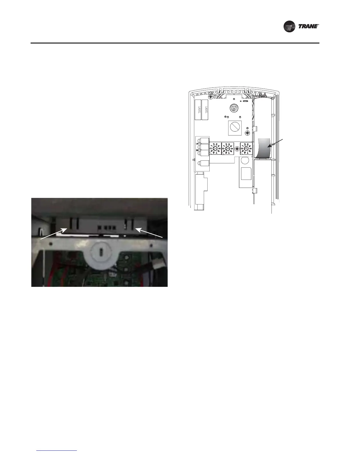
receiver enclosure (see Figure 51) and push upward.
Zone Sensor Settings
Address Setting
The process of establishing communication between a
receiver and sensor is referred to as association. The
following limitations apply:
• Each associated receiver/sensor set that
communicates within the reception range of the
wireless system must have a unique address.
• It is not possible to associate more than one sensor to
a receiver, nor is it possible to associate more than one
receiver to a sensor.
• To associate a receiver and sensor, the two devices
must have their rotary address switches set to the
same address.
Important: Set the addresses before applying power to
the receiver and before removing the
insulation strip (Figure 53) from the sensor.
To set the receiver and sensor addresses:
1. Using a small screwdriver, set the three rotary address
switches (locations S1, S2, S3) on the receiver to an
address between 001 and 999 (see Figure 53). You do
not have to remove the covers to access the rotary
address switches.
Note: Do not use 000 as an address. An address of
000 returns the receiver outputs to their factory
defaults (zone temperature and setpoint
outputs: 72.5°F, removes all association
knowledge, and prevents association with a
sensor.
Figure 51. Retention tabs on underside of receiver
enclosure
Figure 52. Set address before removing insulation strip
from the sensor.
B1 +
WIRELESS
INSTALL
S4
S3
S2
S1
ADDRESS
STATUS
BATTERY
LED5
SIGNAL
LED3
L
E
D
2
LED1
Pb
Pb-FREE
STATUS
LED4
Sensor
Set address before
removing insulation
strip.

 Loading...

