14
T60X
ELECTRICAL CONNECTIONS
SWITCH OFF THE ELECTRICITY SUPPLY AT THE
MAINS.
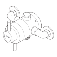
Fig.12 shows a schematic wiring diagram.
The cable entry points are shown in Water/
Cable Entry Points diagram.
The cable can be surface clipped, hidden or via
20mm conduit.
NOTE: Conduit entry can only be from rear.
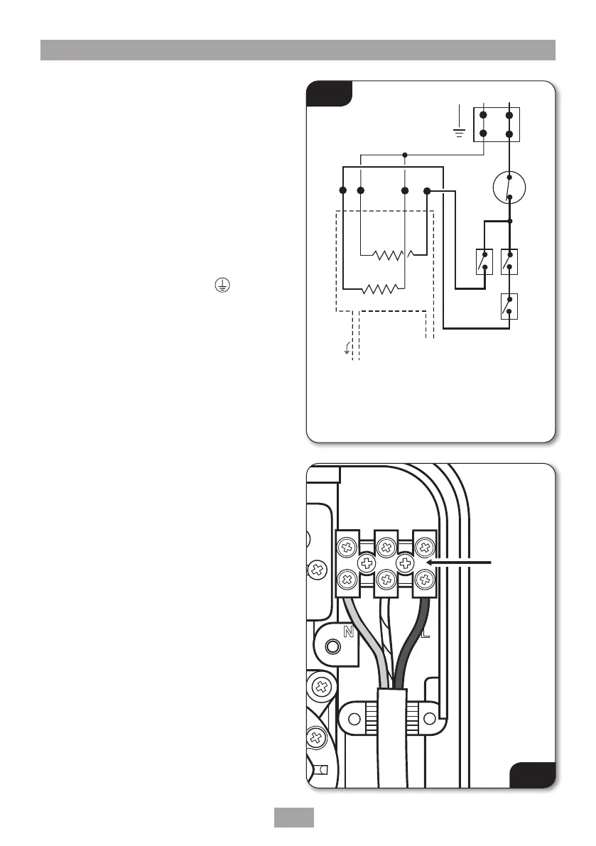
Route the cable into the shower unit and connect
to the terminal block (fig.13) as follows:
Earth cable to terminal marked E
Neutral cable to terminal marked N
Live cable to terminal marked L
Important: Fully tighten the terminal block
screws and check that no cable insulation is
trapped under the screws. Loose connections
can result in cable overheating.
NOTE: The supply cable earth conductor must
be sleeved. The outer sheath of the supply cable
must be stripped back to the minimum.
The supply cable must be secured either by
routing through conduit or in trunking or by
embedding in the wall, in accordance with
current IEE regulations.
The use of connections within the unit, or other
points in the shower circuit, to supply power to
other equipment i.e. extractor fans, pumps, etc.
will invalidate the guarantee.
DO NOT switch on the electricity supply until the
cover has been fitted.
1. Terminal block
2. Thermal cut-out
(main)
3. Microswitches
4. Element
5. Element
6. Microswitch
Fig.12
Fig.13
N
E
1
2
3
4
5
6
Terminal
block

 Loading...