NOTE:
•
At this point the transmission shafts,
crankshaft bearings etc. can be removed.
6 CRANKSHAFT/RODS/PISTONS
CRANKCASES
The upper and lower crankcases are machined as a
matched set and must never be assembled to
non-matching halves.
Before the crankcase halves can be separated, the
engine must be removed from the frame and the
following items must also be removed
1.
Sump.
2.
Engine covers
3.
Alternator.
4.
Starter motor.
5.
Crankshaft position sensor.
Disassembly
A
CAUTION: Failure to follow the correct
screw release sequence may result in
permanent crankcase damage.
1.
Working on the upper crankcase bolts first,
release the bolts in the sequence shown below.
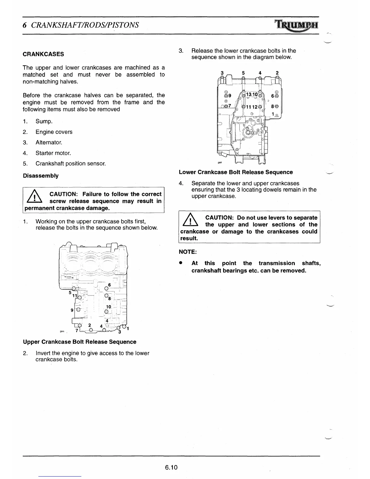
3.
Release the lower crankcase bolts in the
sequence shown in the diagram below.
3 -
5
4
2
pg
13.10.,
6O
t
o
/
?
j
' '
x
,11
1112L
,
M
Lower Crankcase Bolt Release Sequence
4.
Separate the lower and upper crankcases
ensuring that the 3 locating dowels remain in the
upper crankcase.
CAUTION: Do not use levers to separate
•
the upper and lower sections of the
crankcase or damage to the crankcases could
result.
6.10
 Loading...